
Related Manuals for GeoVision GV-EFER3700 Series


Summary of Contents for GeoVision GV-EFER3700 Series
- Page 1 GV-Fisheye IP Camera User's Manual Before attempting to connect or operate this product, please read these instructions carefully and save this manual for future use. FEV123-UM-A...
- Page 2 GeoVision. Every effort has been made to ensure that the information in this manual is accurate. GeoVision, Inc. makes no expressed or implied warranty of any kind and assumes no responsibility for errors or omissions. No liability is assumed for incidental or consequential damages arising from the use of the information or products contained herein.
- Page 3 Starting from V3.0, GV-Fisheye IP Camera (except GV-FER5700 / 5701 / 12203 and GV-EFER3700 Series) supports recording to NAS devices using the Network Neighborhood settings.
-
Page 4: Table Of Contents
Contents Naming and Definition ............vii Caution ..................vii Creating GV-IP Camera’s Login Credentials ......viii Note for Connecting to GV-DVR / NVR / VMS .......ix Note for USB Storage and WiFi Adapter .......ix Note for Recording ..............x Note for Installing Camera ............xi Chapter 1 Introduction ............1 1.1 Key Features ...................... - Page 5 1.7 Connecting the GV-Fisheye Camera ..............48 1.7.1 GV-FE2301 / 4301 ..................48 1.7.2 GV-FE3402 / 3403 / 5302 / 5303 ..............50 1.7.3 Connecting PoE Converter and IR LED Ring for GV-FE3403 / 5303 ..51 1.7.4 GV-FER3402 / 3403 / 5302 / 5303 ............53 1.7.5 GV-FER5700 / 5701 / 12203 ..............55 1.7.6 GV-EFER3700 / EFER3700-W ..............56 Chapter 2 Getting Started ...........58...
- Page 6 Chapter 4 Administrator Mode ...........90 4.1 Video & Motion .....................92 4.1.1 Video Settings ..................93 4.1.2 Motion Detection ..................100 4.1.3 Privacy Mask ..................102 4.1.4 Text Overlay ................... 103 4.1.5 Tampering Alarm ..................104 4.1.6 Visual Automation ................... 106 4.2 I/O Control ......................107 4.2.1 Input Settings ..................
- Page 7 4.8.5 Tools ....................... 150 4.8.6 Language ....................151 Chapter 5 Recording and Playback .........152 5.1 Recording ......................152 5.2 Playback ......................153 5.2.1 Playback from the Memory Card ............. 153 5.2.2 Playback over Network ................157 5.2.3 Access to the Recorded Files through FTP Server ......... 158 5.2.4 Playback of Daylight Saving Time Events ..........
- Page 8 Chapter 7 DVR/NVR/VMS Configurations ......175 7.1 Setting Up IP Cameras on GV-DVR / NVR ............177 7.1.1 Customizing the Basic Settings on GV-DVR / NVR ......... 179 7.2 Setting Up IP Cameras on GV-VMS ..............180 7.3 Remote Monitoring with Multi View ..............182 7.3.1 Connecting to the IP Camera ..............
-
Page 9: Naming And Definition
Naming and Definition GeoVision Analog and Digital Video Recording Software. The GV- GV-DVR / NVR DVR also refers to GV-Multicam System, or GV-Hybrid DVR. GV-VMS GeoVision Video Management System for IP cameras. Caution This caution is only for GV-EFER3700-W. This device complies with Part 15 of the FCC Rules. Operation is subject to the following two conditions: 1. -
Page 10: Creating Gv-Ip Camera's Login Credentials
Creating GV-IP Camera’s Login Credentials The default Administrator and Guest accounts are not supported by the latest firmware anymore. After purchasing a new camera or applying factory defaults, you need to set up a login username and password for that camera. 1. -
Page 11: Note For Connecting To Gv-Dvr / Nvr / Vms
Note for Connecting to GV-DVR / NVR / VMS The GV-Fisheye IP Camera is designed to work with GV-DVR / NVR / VMS, a video management system. Note the following when the camera is connected to GV-DVR / NVR / VMS: 1. -
Page 12: Note For Recording
Note for Recording 1. By default, the images are recorded to the memory card inserted in the GV-Fisheye IP Camera. Make sure the Write recording data into local storage option (see 4.1.1 Video Settings) is enabled. If this option is disabled, the camera will stop recording to the memory card while the live view is accessed through Web browsers or other applications. -
Page 13: Note For Installing Camera
Note for Installing Camera When installing GV-FER outdoor models, be sure that: 1. The camera is set up above the junction box to prevent water from entering the camera along the cables. 2. Any PoE, power, audio and I/O cables are waterproofed using waterproof silicon rubber or the like. - Page 14 4. The silica gel bag loses it effectiveness when the dry camera is opened. To prevent the lens from fogging up, use the supplied adhesive tap and replace the silica gel bag every time you open the camera, and conceal the gel bag in camera within 2 minutes of exposing to open air.
-
Page 15: Chapter 1 Introduction
Introduction Chapter 1 Introduction The fisheye camera allows you to monitor all angles of a location using just one camera. It can be installed to the ceiling, wall, wall corner and pole. The distorted hemispherical image of the fisheye camera will be converted into the conventional rectilinear projection. Without installing any software, you can watch live view and utilize functions such as motion detection, privacy mask, and alert notification through the Web interface. -
Page 16: Key Features
1.1 Key Features Image sensor Camera Model Image Sensor GV-FE2301 GV-FE4301 1/2.5’’ progressive scan CMOS GV-FE5302 / 5303 GV-FER5302 / 5303 GV-FE3402 / 3403 1/3.2’’ progressive scan CMOS GV-FER3402 / 3403 GV-EFER3700 / EFER3700-W 1/2.8” progressive scan super low lux CMOS GV-FER5700 1/1.8’’... - Page 17 Introduction Day and night function Camera Model Day / Night function GV-FE2301 / 4301 Electronic GV-FE3402 / 3403 GV-FE5302 / 5303 GV-FER3402 / 3403 GV-FER5302 / 5303 Removable IR-cut filter GV-EFER3700 / EFER3700-W GV-FER5700 / 5701 / 12203 GV-UNFE2503 / 2502 ...
- Page 18 Mini USB slot for WiFi adapter or USB hard drive (GV-FE3402 / 3403 / 5302 / 5303) USB slot for WiFi adapter or USB hard drive (GV-FER5700 / 5701) One sensor input and alarm output (GV-FE2301 / 4301, GV-FER5700 / 5701 / 12203 and GV-EFER3700 / EFER3700-W) ...
-
Page 19: Packing List
Introduction 1.2 Packing List GV-FE2301 / 4301 Fisheye Camera Support Bracket x 3 Camera Cover (Hard Ceiling Mount) Camera Cover (In-Ceiling Mount) Screw (Hard Ceiling Mount) x 3 Screw (In-Ceiling Mount) x 3 ... - Page 20 GV-FE3402 / 5302 and GV-FE3403 / 5303 Fisheye Camera Support Bracket x 3 Camera Cover (Hard Ceiling Mount) Camera Cover (In-Ceiling Mount) Screw (Hard Ceiling Mount) x 3 Screw (In-Ceiling Mount) x 3 ...
- Page 21 Introduction PoE Converter set (including 1 module, 1 DC Power Y-cable, 1 RJ-45 cable and 3 PoE Screws) (GV-FE3403 / 5303 only) Installation Sticker Power Adapter Download Guide GV-Fisheye IP Dome Hardware Installation Guide Warranty Card Note: The power adapter can be excluded upon request.
- Page 22 GV-FER3402 / 5302 and GV-FER3403 / 5303 Fisheye Camera Support Bracket x 3 Camera Cover (Hard Ceiling Mount) Camera Cover (In-Ceiling Mount) Screw (Hard Ceiling Mount) x 3 Screw (In-Ceiling Mount) x 3 ...
- Page 23 Introduction Terminal Block x 2 Power Cable (female) (male) Installation Sticker IR Power Adapter (DC 12V, 3.5A, GV- FER3403 / 5303 only) Cable Connector Silica Gel Bag and Adhesive Tape x 2 Power Adapter (DC 12V, 1.25A) ...
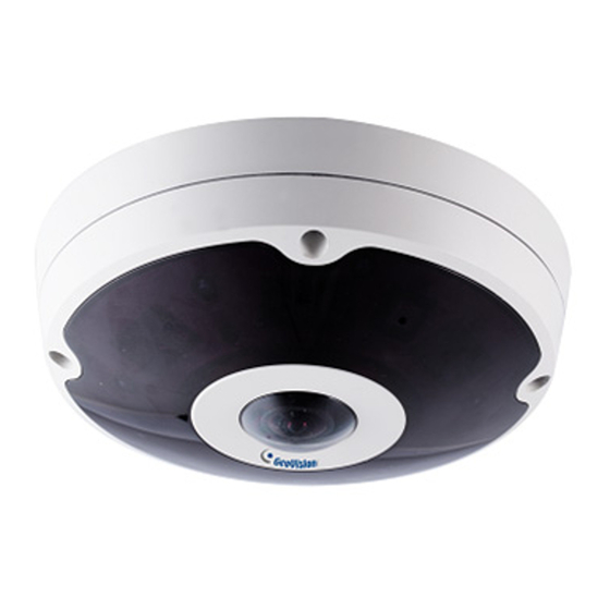
- Page 24 GV-EFER3700 / EFER3700-W H.265 Fisheye Camera Torx Wrench Screw x 2 Screw Anchor x 2 Silica Gel Bag x 2 Terminal Block (3-pin) Installation Sticker Power Adapter (only for GV-EFER3700-W) Download Guide ...
- Page 25 Introduction GV-FER5700 / 5701 / 12203 Fisheye Camera Back Plate Plate Screw x 3 Plastic Screw Anchor x 3 Torx Wrench RJ-45 Connector Data Cable Terminal Block Installation Sticker Ruler ...
- Page 26 GV-UNFE2503 / 2502 GV-UNFE2503 Installation Sticker (for GV-UNFE2503) GV-UNFE2502 Installation Sticker (for GV-UNFE2502) Main Body Adhesive Tape Main Body Mount M2 Screw M3 Screw x 2 Warning Label Download Guide ...
-
Page 27: System Requirement
Introduction 1.3 System Requirement To operate the camera through a web browser, make sure your PC has good network connection, and meet the following system requirement: 64-bit Windows 7 / 8 / 8.1 / Server 2008 R2 / Server 2012 R2 GV-VMS V15.11.3 with patch files or later GV-DVR / NVR Version... -
Page 28: Optional Accessories
1.4 Optional Accessories Optional devices can expand the capabilities and versatility of your GV-Fisheye Camera. Contact your dealer for more information. Name Details GV-PA191 The GV-PA191 is a Power over Ethernet (PoE) adapter designed to provide power to the IP device through a single Power over Ethernet (PoE) Ethernet cable. -
Page 29: Physical Description
Introduction 1.5 Physical Description 1.5.1 GV-FE2301 / 4301 To access the Default button, LED indicators and micro SD card slot, unscrew the screws indicated below and then remove the camera cover. Figure 1-1: GV-FE2301 / 4301 Name Function Lens Receives image inputs. Speaker Talks to the surveillance area from the local computer. -
Page 30: Gv-Fe3402 / 3403 / 5302 / 5303
1.5.2 GV-FE3402 / 3403 / 5302 / 5303 Figure 1-2 Name Function Lens Receives image inputs. Speaker Talks to the surveillance area from the local computer. Microphone Receives the sound from the camera. Status LED Indicates whether the device is booted successfully or not. LAN / PoE Connects to a 10/100 Ethernet or PoE. -
Page 31: Gv-Fer3402 / 3403 / 5302 / 5303
Introduction 1.5.3 GV-FER3402 / 3403 / 5302 / 5303 Figure 1-3 Name Function Lens Receives image inputs. Speaker Talks to the surveillance area from the local computer. Microphone Receives the sound from the camera. LEDs See the table below for details. Resets all configurations to default factory settings. - Page 32 Note: For GV-FER3402 / 3403 / 5302 / 5303, a silica gel bag is attached to the inside of the camera cover. The silica gel loses effectiveness after you open the camera cover. To prevent the lens from fogging up, it is highly recommended to replace the silica gel bag every time you open the camera.
- Page 33 Introduction PoE Cable For GV-FER3402 / 3403 / 5302 / 5303, the PoE connector may be one of the following types: Type 1 42.8 mm (1.7") 19.6 (0.8") Ø Type 2 58.5 mm (2.3") Ø 28.2 (1.1")
-
Page 34: Gv-Efer3700 / Efer3700-W
1.5.4 GV-EFER3700 / EFER3700-W Figure 1-5 Name Function Indicates whether the camera is booted successfully or not. Status LED Flashes when the camera is loading default settings. Power LED Indicates whether the camera is powered on or off. Resets all configurations to default factory settings. See Default Button 6.3 Restoring to Factory Default Settings. - Page 35 Introduction Only for GV-EFER3700-W, connects the camera to the WPS Button WiFi router wirelessly. For detailed instructions, see WPS Button below. WiFi Status LED Flashes when the camera is mapping with the WiFi router. Indicates whether the camera’s WiFi module is powered WiFi Power LED on or off.
-
Page 36: Gv-Fer5700 / 5701
1.5.5 GV-FER5700 / 5701 Figure 1-6 Name Function Microphone Receives the sound from the camera. Flashes when the camera is powering on and loading Status LED default settings. Resets all configurations to default factory settings. See Default Button 6.3 Restoring to Factory Default Settings. Data Cable Connector Waterproofs the data cable. -
Page 37: Gv-Fer12203
Introduction 1.5.6 GV-FER12203 Figure 1-7 Name Function Microphone Receives the sound from the camera. Flashes when the camera is powering on and loading Status LED default settings. Data Cable Connector Waterproofs the data cable. Lens Receives image inputs. Inserts a micro SD memory card (SD / SDHC / SDXC / Micro SD Card Slot UHS-I) to store recorded data. -
Page 38: Gv-Unfe2503 / 2502
1.5.7 GV-UNFE2503 / 2502 GV-UNFE2503 GV-UNFE2502 Figure 1-8 Name Function Lens Receives images. Microphone Receives sounds. IR LED Provides infrared illumination under low-light situations. RJ12 Cable Connects the camera lens and main body. - Page 39 Introduction IR LED Power Connects the IR LED power cable. Connector Camera Ring Fastens the camera to the desired surface. Use the camera’s RJ12 cable to connect the camera lens RJ12 Port and main body. Turns on (green) when the camera lens and main body RJ12 Status LED are connected.
-
Page 40: Installation
1.6 Installation The fisheye camera is designed to be mounted on the ceiling, wall or ground. There are two ways to mount the camera on the ceiling, Hard Ceiling Mount and In-Ceiling Mount. Make sure the ceiling has enough strength to support the fisheye camera. Note: To re-focus your camera, follow the instruction below. -
Page 41: Hard Ceiling Mount
Introduction 1.6.1 Hard Ceiling Mount In this section, we introduce three types of hard-ceiling mounts: General Hard-Ceiling Mount, GV-FER5700 / 5701 / 12203 and GV-EFER3700 / EFER3700-W. 1.6.1.1 General Hard-Ceiling Mount Without IR LED Ring With IR LED Ring Note: This hard-ceiling mount is not applicable to GV-FER5700 / 5701 / 12203 and GV- UNFE2503 / 2502. - Page 42 2. At the 3 red dots, drill a hole slightly smaller than the plastic screw anchors provided. 3. Insert the 3 plastic screw anchors in the drilled holes. 4. Secure the fisheye camera with the 3 hard ceiling mount screws provided. Figure 1-10 5.
- Page 43 Introduction d. Move the components toward the RJ-45 connector, secure item 1 to the Rubber Seal Ring of the camera data cable and secure item 2 to item 1 tightly. IMPORTANT: Item 1 must be secured tightly to waterproof the cable. 6.
- Page 44 B. Place the IR LED ring on top of the camera and tighten the screws with the torx wrench provided. Figure 1-15 Caution: An operating IR LED ring may reach high temperatures. Disconnect the power supply and allow the IR LED ring to cool down before handling the device.
-
Page 45: Gv-Fer5700 / 5701 / 12203
Introduction 1.6.1.2 GV-FER5700 / 5701 / 12203 1. Paste the installation sticker to the ceiling board. 2. At the 3 dots, drill a hole slightly smaller than the plastic screw anchors provided. Figure 1-16 3. Insert the 3 plastic screw anchors in the drilled holes. 4. - Page 46 5. Open the camera cover by unscrewing the indicated screws. Figure 1-18 6. Connect the Ethernet cable. a. Unplug the LAN / PoE connector and prepare an Ethernet cable with only one RJ- 45 connector. Figure 1-19 b. Thread the Ethernet cable through the opening into the camera and through the plug and cap as shown below.
- Page 47 Introduction d. Attach the supplied RJ-45 connector to the Ethernet cable, and plug the connector into the LAN / PoE port. e. Loosen the screw on the cable holder and thread the cable under the cable holder. Figure 1-21 7. Connect the supplied data cable if needed. a.
- Page 48 c. Slide the hexagon washer through the cable, and then tighten the washer. Hexagon washer Figure 1-24 d. Plug the pins of the cable to the camera as shown below. Figure 1-25 8. Secure the camera to the back plate by tightening the 4 screws as shown below. The cables can be threaded through the cable opening on the side or through the ceiling board.
-
Page 49: Gv-Efer3700 / Efer3700-W
Introduction 1.6.1.3 GV-EFER3700 / EFER3700-W 1. Remove the back plate. 2. Paste the installation sticker to the ceiling board. 3. Drill holes in the indicated areas on the installation sticker. Figure 1-27 4. Insert the 2 screw anchors in the drilled holes. - Page 50 5. Secure the back plate onto the ceiling board with the 2 screws provided. If you want to thread the camera cables through the ceiling board, you can cut a cable opening as shown below. Make sure to cut the cable opening slightly larger than the RJ-45 plug of the camera cable.
-
Page 51: Waterproofing The Cable
Introduction 8. Secure the camera cover and tighten the 4 screws. 9. Connect the camera cables. For details, refer to 3. Connecting the Camera in the Quick Start Guide. 1.6.1.4 Waterproofing the Cable Waterproof the Ethernet cable of GV-EFER3700 / EFER3700-W by using the supplied waterproof rubber set. -
Page 52: In-Ceiling Mount
1.6.2 In-Ceiling Mount In this section, we introduce two types of in-ceiling mounts: General In-Ceiling Mount and GV-UNFE2503 / 2502. 1.6.2.1 General In-Ceiling Mount In-Ceiling Mount allows the camera to be mounted into the ceiling, revealing a small portion of the camera. In-Ceiling Mount requires the ceiling board to be between 0.5 – 3.0 cm (0.2 – 1.18 in) thick. - Page 53 Introduction 2. Align the 3 support brackets with the holes on the back of the camera as shown below and secure using the in-ceiling mount screws provided. Figure 1-36 3. For outdoor GV-Fisheye Cameras (GV-FER3402 / 5302), install the supplied cable connector to waterproof the cable.
- Page 54 5. On the back side, make sure the black plastic clips are slightly above the ceiling board and pointing outward. Figure 1-38 6. From the front side of the camera, tighten the screws. Figure 1-39 7. Connect the camera with power, network and other wires. For details, see 1.7 Connecting the GV-Fisheye Camera.
-
Page 55: Gv-Unfe2503 / 2502
Introduction 1.6.2.2 GV-UNFE2503 / 2502 The GV-UNFE2503 / 2502 is designed for outdoors. You can install the camera lens behind a ceiling. For GV-UNFE2502, you can also install the camera lens behind a wall. Figure 1-41 Note: It is recommended to have the camera lens installed behind a ceiling board with the thickness between 3 mm and 30 mm. - Page 56 3. Using the 2 holes / 1 hole as the starting position, drill or cut out the shape of the template sticker with the tool of your choice. Figure 1-43 4. Only for GV-UNFE2503, remove the IR LED power cable from the camera lens by rotating the silver ring.
- Page 57 Introduction Note: You must remove the IR LED power cable and / or the camera ring in order to secure the camera lens to the desired surface. 6. Only for GV-UNFE2502, assemble the mounting rail to the camera lens. Figure 1-46 7.
- Page 58 8. Assemble the camera ring to the camera lens by rotating the ring. Adjust the position of the lens before fully securing the ring. Figure 1-48 Note: The side of the camera ring with the protruding notches must face the wall or ceiling.
- Page 59 Introduction 10. Place the main body mount where you want to install it, and secure the mount using one of the methods below. Insert and tighten the two supplied M3 screws. Figure 1-50 Paste the main body adhesive tape on the bottom side of the main body mount. Figure 1-51 11.
- Page 60 13. Connect the main body to the network and supply power via the PoE cable. Status LED Figure 1-53 14. Install the camera on a network. See 2.1 Installing on a Network.
-
Page 61: Standard Wall Mount And Ground Mount
Introduction 1.6.3 Standard Wall Mount and Ground Mount To mount the camera on a wall, follow the instructions in 1.6.1 Hard Ceiling Mount. Figure 1-54 Note: GV-UNFE2502 also supports wall mount, while GV-UNFE2503 doesn’t. For how to mount the GV-UNFE2502 on the wall, refer to GV-UNFE2503 / 2502, 1.6.2 In-Ceiling Mount. -
Page 62: Connecting The Gv-Fisheye Camera
1.7 Connecting the GV-Fisheye Camera 1.7.1 GV-FE2301 / 4301 GV-FE series come with a 5-pin data cable that allows you to connect to the power and any I/O devices. Digita l Output (Re d) GND (Bla ck) Digita l Input (Brown) AC 24V / DC + (Yellow) AC 24V / DC - (Ora nge ) E the rne t (P oE ) - Page 63 Introduction Connecting to Power You can connect to power using either the power adapter provided or a Power over Ethernet (PoE) adapter. To connect to power using the power adapter, follow the steps below to connect the orange and yellow wires of the camera to the 3-pin or 2-pin terminal block provided.
-
Page 64: Gv-Fe3402 / 3403 / 5302 / 5303
1.7.2 GV-FE3402 / 3403 / 5302 / 5303 Figure 1-59 Remove the camera cover with the supplied torx wrench. Supply power and network to the camera with one of the following methods: Power adapter: plug in the power adapter and connect a standard network work cable. -
Page 65: Connecting Poe Converter And Ir Led Ring For Gv-Fe3403 / 5303
Introduction 1.7.3 Connecting PoE Converter and IR LED Ring for GV-FE3403 / 5303 To install a PoE converter, follow the steps below. Note: Instead of installing the PoE converter, you can connect the camera to a PoE switch and the IR LED ring with a power adapter (optional accessory). Figure 1-60 Connect the PoE converter to a PoE switch with a standard network cable. - Page 66 Plug one of the PoE converter’s terminal blocks to the camera and the other one to the IR LED ring. IMPORTANT: It is advised to shorten the IR LED ring’s wire to approximately 20 cm for it to fit inside the PoE converter. 20cm Figure 1-61 Secure the camera to the PoE converter with the supplied screws.
-
Page 67: Gv-Fer3402 / 3403 / 5302 / 5303
Introduction 1.7.4 GV-FER3402 / 3403 / 5302 / 5303 Figure 1-64 Remove the camera cover with the supplied torx wrench. Supply power to the camera with one of the following: A. Power adapter: see Assembling the Power Adapter later in this section. B. - Page 68 Assembling the Power Adapter Insert the supplied power cable into the supplied waterproof rubber and plug it into the camera. Figure 1-65 Insert the power cable into the supplied female terminal block as illustrated and plug it into the terminal block connector in the camera. Figure 1-66 Insert the power wires at the other end into the male terminal block as illustrated and plug it to the power adapter.
-
Page 69: Gv-Fer5700 / 5701 / 12203
Introduction 1.7.5 GV-FER5700 / 5701 / 12203 GV-FER5700 / 5701 / 12203 comes with a data cable that allows you to connect to the power adapter, WiFi adapter or USB hard drive, microphone, speaker, and any I/O devices. Figure 1-68 Note: AC 24V is not supported by GV-FER5700 / 5701. -
Page 70: Gv-Efer3700 / Efer3700-W
1.7.6 GV-EFER3700 / EFER3700-W GV-EFER3700 / EFER3700-W come with a data cable that allows you to connect to the power, microphone, speaker, and any I/O devices. Figure 1-69 Connecting to Power There are two ways to supply power to the camera: ... - Page 71 Introduction Connecting to I/O Devices The camera supports one digital input and one digital output of dry contact. Pin Function Digital Output Digital Input Figure 1-70 Voltage Load Expansion (Optional) The camera can only drive a maximum load of 200mA 5V DC. To expand the maximum voltage load to 10A 250V AC, 10A 125V AC or 5A 100V DC, connect the camera to a GV- Relay V2 module (optional product) as illustrated below.
-
Page 72: Chapter 2 Getting Started
Chapter 2 Getting Started This section provides basic information to get the camera working on the network. 2.1 Installing on a Network These instructions describe the basic connections to install the camera on the network. Using a standard network cable, connect the camera to your network. Connect power using one of the methods: ... -
Page 73: Checking The Dynamic Ip Address
Getting Started 2.1.1 Checking the Dynamic IP Address Follow the steps below to look up the IP address and access the Web interface. Download and Install the GV-IP Device Utility program from the company website. Note: The PC installed with GV-IP Device Utility must be under the same LAN as the camera you wish to configure. -
Page 74: Assigning An Ip Address
By default, GV-Fisheye Camera that is connected to LAN without a DHCP server, is assigned with the static IP address 192.168.0.10. Follow the steps below to assign a new IP address to avoid IP conflict with other GeoVision devices. Note: The computer used to set the IP address must be under the same network with the camera. - Page 75 Getting Started IMPORTANT: If Dynamic IP Address or PPPoE is enabled, you need to know which IP address the camera will get from the DHCP server or ISP to log in. If your camera in installed in a LAN, use the GV-IP Device Utility to look up its current dynamic address.
-
Page 76: Configuring The Wireless Connection
2.1.3 Configuring the Wireless Connection Wireless settings are only applicable to GV-FE3402 / 3403 / 5302 / 5303, GV-FER5700 / 5701 / 12203 and GV-EFER3700-W. Insert a WiFi adapter to the camera and follow the steps below to set up a wireless connection to your camera. Note: GV-EFER3700-W has a built-in WiFi antenna and supports the WPS function. - Page 77 Getting Started D. Select the Authentication Type using the drop-down list. You can also obtain this information by clicking the Access Point Survey button. E. Type the WPA-PSK Pre-shared Key or WEP depending on the encryption setting for the Access Point. F.
-
Page 78: Configuring The Basics
B. Select Wireless for Optional Network Type. C. To use a dynamic IP address assigned by the DHCP server, select Dynamic IP address. To use a fixed IP address, select Static IP address and type the IP address information. 5. -
Page 79: Chapter 3 Accessing The Camera
Accessing the Camera Chapter 3 Accessing the Camera Two types of users are allowed to log in to the camera: Administrator and Guest. The Administrator has unrestricted access to all system configurations, while the Guest has the access to live view and network status only. 3.1 Accessing Your Surveillance Images Once installed, your camera is accessible on a network. -
Page 80: Functions Featured On The Main Page
To enable the updating of images in Microsoft Internet Explorer, you must set your browser to allow ActiveX Controls and perform a one-time installation of GeoVision’s ActiveX component onto your computer. 3.2 Functions Featured on the Main Page This section introduces the features of the Live View window and Network Status on the main page. -
Page 81: The Live View Window
Accessing the Camera 3.2.1 The Live View Window Internet Explorer When accessing the camera live view using Internet Explorer, the following window appears. Figure 3-3... - Page 82 No. Name Function 1 Play Plays live video. 2 Stop Stops playing video. Talks to the surveillance area from the local computer. Click the Push to talk button (from the pop-up menu) for the camera to 3 Microphone switch between audio transmission and reception, where only one party can speak at a time.
- Page 83 Accessing the Camera Non-IE Browsers When accessing the camera live view using Google Chrome, Firefox or Safari, the following window appears. The following functions are not supported using non-IE browsers: Control panel, function buttons, Motion Detection, Tampering Alarm, Visual Automation, Text Overlay, and Two-Way Audio.
-
Page 84: Fisheye View
3.2.2 Fisheye View To enable the fisheye options, right-click the live view and select Geo Fisheye. Right-click the image again and select Fisheye Option to see the following options. Image Alignment: By default, the image should be properly aligned already. If not, ... - Page 85 The circular source image of GV-FE2301 / 4301 should be centered and slightly cropped on all four edges. If the image is not centered, please contact your sales representative and send your device back to GeoVision for adjustment. To determine whether your device needs adjustment, measure the length of a longer cropped edge and the length of that entire edge.
- Page 86 Dual 180 degree: 2 180º views Single view: 1 PTZ view Figure 3-7 Note: When wall mount is selected for Camera Position, only one 180º view will be displayed. Camera Position: Select Ceiling, Wall or Ground according to where the camera is ...
- Page 87 Accessing the Camera Note: The default setting for Hardware Acceleration is enabled for GPU dewarping and it automatically detects the Screen Ratio Setting. If you clear Hardware Acceleration, it changes to CPU dewarping and you can select the Screen Ratio Setting. You can drag and drop PTZ view or 180º...
-
Page 88: The Control Panel Of The Live View Window
3.2.3 The Control Panel of the Live View Window To open the control panel of the Live View window, click the arrow button on top of the viewer. You can access the following functions by using the left and right arrow buttons on the control panel. - Page 89 Accessing the Camera [I/O Control] Provides a real-time graphic display of the input and output status. You can force the output to be triggered by double-clicking its icon. [Alarm Notify] Displays images captured upon sensor triggers and/or motion detection. For this function to work, you must configure the Alarm Notify settings first.
- Page 90 Color Temperature: Adjust the camera image to have a warmer or cooler color tone. Note this function is available for GV-FER5700 / 5701 and GV-EFER3700 Series, and only appears when you choose Manual for White Balance. Tint: Move the slider to remove undesired color cast for a more neutral color. Note this ...
- Page 91 Accessing the Camera Denoise: Reduces image noise especially under low-light conditions. The higher the denoise value, the stronger the effect. Wide Dynamic Range: adjusts and generates clear live view when the scene contains very bright and very dark areas at the same time. Select Auto (Strong) to bring out details in the darks areas of the scene, select Auto (Weak) to bring out less detail in the dark area and at the same time keep the bright areas from overexposure, or select Auto (Normal) for a balanced effect.
-
Page 92: Snapshot Of A Live Video
3.2.4 Snapshot of a Live Video To take a snapshot of live video, follow these steps: 1. Click the Snapshot button (No. 5, Figure 3-3). The Save As dialog box appears. 2. Specify Save in, type the File name, and select JPEG or BMP as Save as Type. You may also choose whether to display the name and date stamps on the image. -
Page 93: Wide Angle Lens Dewarping
Accessing the Camera 3.2.6 Wide Angle Lens Dewarping The fisheye source view is curved especially near the edges. Use this function to reduce the warping of live view. 1. Right-click on the live view to display a drop-down list. 2. Select Wide Angle Setting. The Wide Angle Dewarping Setting window appears. Figure 3-11 3. -
Page 94: Picture-In-Picture And Picture-And-Picture View
3.2.7 Picture-in-Picture and Picture-and-Picture View Two types of close-up views are available to provide clear and detailed images of the surveillance area: Picture-in-Picture (PIP) and Picture-and Picture (PAP). After entering the live view window, the image is displayed in PIP mode by default. The PIP and PAP views can only be displayed on the hemispherical source image. - Page 95 Accessing the Camera Picture-and-Picture View With the Picture and Picture (PAP) view, you can create a split video effect with multiple close-up views on the image. A total of 7 close-up views can be defined. Figure 3-13 Right-click the live view and select PAP. A row of three inset windows appears at the bottom.
-
Page 96: Object Tracking
3.2.8 Object Tracking You can track moving objects in fisheye live view. The function is only available when the fisheye camera mode is set to be Geo Fisheye: 360 degree. When motion is detected, the top-right channel will start tracking the moving object and in the 360 degree view at the bottom, the moving object will be highlighted. - Page 97 Accessing the Camera Use the options below to customize object tracking. Mask Region: Use the mouse to outline a mask region where motion will be ignored. Object Size: Click the button to pause the live view and then use the mouse ...
-
Page 98: Alarm Notification
3.2.9 Alarm Notification After input triggers and motion detection, you can be alerted by a pop-up live video and view up to four captured images. Captured Images Pop-up live video Figure 3-16 To configure this function, click the Show System Menu button (No. 11, Figure 3-3), and select Alarm Notify. - Page 99 Accessing the Camera Auto Snapshot: The snapshot of live video is taken every 5 seconds on motion and input-triggered detection. File Path: Assigns a file path to save the snapshots. Note: The Administrator can adjust the motion detection area by using the Motion Detection function.
-
Page 100: Video And Audio Configuration
3.2.10 Video and Audio Configuration You can enable the microphone and speaker for two-way audio communication and set the number of frames to keep for live view buffer. Click the Show System Menu button (No. 9, Figure 3-3), and select Video and Audio Configuration. Camera: Sets the number of frames to keep in live view buffer. -
Page 101: Remote Configuration
Accessing the Camera 3.2.11 Remote Configuration You can view the connection status of the central monitoring stations and upgrade firmware over the network. Click the Show System Menu button (No. 9, Figure 3-3), and select Remote Config. The Remote Config dialog box will appear. [Firmware Upgrade] In this tab, you can upgrade the firmware over the network. -
Page 102: I/O Control
3.2.14 I/O Control The I/O Control window provides real-time graphic displays of camera status, I/O status, and alarm events. Additionally, you can remotely force output to be triggered. Note: I/O Control settings are only supported by GV-FE2301 / 4301, GV-FER5700 / 5701 / 12203 and GV-EFER3700 / EFER3700-W. -
Page 103: Visual Automation
Accessing the Camera 3.2.15 Visual Automation This function is only supported by GV-FE2301 / 4301, GV-FER5700 / 5701 / 12203 and GV- EFER3700 / EFER3700-W. The Visual Automation allows you to change the current state of the electronic device by simply clicking on its image, e.g. turning the light ON. This feature is only available when the Visual Automation is set ahead by the Administrator. -
Page 104: Chapter 4 Administrator Mode
Chapter 4 Administrator Mode The Administrator can access the system configuration through the network. Eight categories of configurations are involved in the system configuration: Video and Motion, I/O Control, Events and Alerts, Monitoring, Recording Schedule, Remote ViewLog, Network and Management. Figure 4-1... - Page 105 Administrator Mode List of Menu Options Find the topic of interest by referring to the section number prefixed to each option. IMPORTANT: The available options and functions may vary among camera models and firmware versions. 4.1.1 Video Settings 4.1.2 Motion Detection 4.1.3 Privacy Mask 4.1 Video and Motion 4.1.4 Text Overlay...
-
Page 106: Video & Motion
Video Resolution and Streaming 2 / 3. Note: Streaming 3 is only supported by GV-FER5700 / 5701 and GV-EFER3700 series. By default, Streaming 3 is disabled. This section includes video image settings and how the images can be managed by using... -
Page 107: Video Settings
Administrator Mode 4.1.1 Video Settings Figure 4-2... - Page 108 640 x 480 Main 1920 x 1080 GV-UNFE2502 / 30 fps 2503 640 x 480 Flicker: Choose the Flicker Hz value between 60 Hz or 50 Hz. This function is only supported by GV-FER5700 / 5701 and GV-EFER3700 Series.
- Page 109 Note: To enable Smart Streaming, only supported by GV-FER5700 / 5701 / 12203 and GV-EFER3700 Series, it is required to use either GV-NVR V8.7.0 or GV-VMS V16.10.3 and later versions. For details, see the technical notice.
- Page 110 This function is not available for GV-FER5700 / 5701 / 12203 and GV-EFER3700 Series. [Record Settings] Note for GV-FER5700 / 5701 / 12203 and GV-EFER3700 Series, see Recording Settings in 4.4 Monitoring to adjust the setting.
- Page 111 [Text Overlay Settings (OSD)] Displays camera name, date, and/or time on the live view and recorded videos when viewing through GeoVision software and third-party software through ONVIF and RTSP. Name: Type the camera name.
- Page 112 [LED Control] Select Disable if you do not want to use the System Status LED (No. 8, Figure 1-2). [Enable SDK] Select Enable to activate SDK. This function is not available for GV-FER5700 / 5701 / 12203 and GV-EFER3700 Series. [Special View Setting] D/N: Sets the Day/Night mode of the camera.
- Page 113 Administrator Mode [Advanced Setting] Note this function is only supported by GV-FER5700 / 5701 and GV- EFER3700 Series. You can enable Advanced Encryption Standard (AES) to protect the streamed contents. Figure 4-4 Note: This function only works with GV-VMS V18.1 and GV-DVR / NVR V8.8 or later versions.
-
Page 114: Motion Detection
4.1.2 Motion Detection Motion detection is used to generate an alarm whenever movement occurs in the video image. You can configure up to 8 areas with different sensitivity values for motion detection. Figure 4-5 The motion detection function is disabled by default. Follow the steps below to set up motion detection. - Page 115 For related settings, see 4.4 Monitoring. Note: 1. The I/O settings are only available for GV-FE2301 / 4301, GV-FER5700 / 5701 / 12203 and GV-EFER3700 Series. 2. Set duration is only supported by GV-FER5700 / 5701 / 12203 / EFER3700 Series.
-
Page 116: Privacy Mask
The Privacy Mask function is used to block out sensitive areas on live view and recorded clips for the camera connecting to GeoVision software. This feature is ideal for locations where displays, keyboard sequences (e.g. passwords), and for anywhere else you don’t sensitive information visible. -
Page 117: Text Overlay
Administrator Mode 4.1.4 Text Overlay The Text Overlay allows you to overlay any text in any place on the camera view. Up to 16 text messages can be created on one camera view. The overlaid text will be saved in the recordings. -
Page 118: Tampering Alarm
4.1.5 Tampering Alarm The Tampering Alarm is used to detect when the camera is being physically tampered with. An alarm can be generated when the camera is moved, covered up, or out of focus. The alarm types include triggering the output device, e-mail alert and notifying the connected GV-Center V2, GV-Vital Sign Monitor, GV-DVR / NVR / VMS. - Page 119 Administrator Mode To configure the tampering alarm: 1. Select Enable. 2. If you want the camera to ignore any movement or scene change in certain areas, click button to drag areas on the camera view. 3. Select the desired detection sensitivity by moving the slider. The higher the value, the more sensitive the camera is to scene changes.
-
Page 120: Visual Automation
When you click on the image of the electronic device, you can change its current state, e.g. turning the light on. Note: Visual Automation settings are only supported by GV-FE2301 / 4301, GV-FER5700 / 5701 / 12203 and GV-EFER3700 Series. Figure 4-10 1. Select the Enable option. -
Page 121: I/O Control
The I/O wires connected to the camera provide the interface for one input device and one output device. Note: The I/O settings are only supported by GV-FE2301 / 4301, GV-FER5700 / 5701 / 12203 and GV-EFER3700 Series. 4.2.1 Input Settings To activate the sensor input, select Enable. -
Page 122: Output Settings
4.2.2 Output Settings Select Enable to start the output device. Choose the output signal that best suits the device you are using: N/O (Open Circuit), N/C (Grounded Circuit), N/O Toggle, N/C Toggle, N/O Pulse or N/C Pulse. For Toggle output type, the output continues to be triggered until a new input trigger ends the output. -
Page 123: Events & Alerts
Administrator Mode 4.3 Events & Alerts The Administrator can set up the following alert methods to receive notifications when motion is detected or I/O devices are triggered: 1. Send a captured still image by e-mail or FTP. 2. Notify Center Monitoring Station, Center V2, Vital Sign Monitor or GV-GIS, by video or text alerts. - Page 124 [Enable] Select to enable the e-mail function. Sever URL/IP Address: Type the SMTP Server’s URL address or IP address. Server Port: Type the SMTP Server’s port number. Or keep the default value 25. From email address: Type the sender’s e-mail address. ...
-
Page 125: Ftp
Administrator Mode 4.3.2 FTP You can also send the captured images to a remote FTP server as alerts. Figure 4-15 [Upload to an FTP Server] Enable: Select to enable the FTP function and then select Active Mode or Passive Mode, depending on the setting of your FTP server. - Page 126 By default, the Keep Day is set to 1. Important: To send FTP alert upon motions, be sure to set up the detection area on the Motion Detection page. Digital Input settings are only supported by GV-FE2301 / 4301, GV-FER5700 / 5701 / 12203 and GV-EFER3700 Series.
- Page 127 Administrator Mode [Act as FTP Server] Enable FTP access to GV-IPCAM: The camera acts as an FTP server, enabling users to download AVI files. The memory card must be inserted for the camera to act as an FTP server. Use alternative port: The default port is set to 21.
-
Page 128: Center V2
To notify the Center V2 Server upon motions, be sure to set up the detection area on the Motion Detection page. The input trigger function is only supported by GV-FE2301 / 4301, GV-FER5700 / 5701 / 12203 and GV-EFER3700 Series. Figure 4-16... - Page 129 Administrator Mode To enable the Center V2 connection: 1. Activate Link: Enable the monitoring through Center V2. 2. Host Name or IP Address: Type the host name or IP address of Center V2. 3. Port Number: Match the port to Port 2 on Center V2. Or keep the default value 5551. For details, see 8.1 Center V2.
-
Page 130: Vital Sign Monitor
To notify the Vital Sign Monitor upon motions, be sure to set up the detection area on the Motion Detection page. Input trigger is only available for GV-FE2301 / 4301, GV-FER5700 / 5701 / 12203 and GV-EFER3700 Series. Figure 4-17... - Page 131 Administrator Mode To enable the Vital Sign Monitor connection: 1. Activate Link: Enable the monitoring through Vital Sign Monitor. 2. Host Name or IP Address: Type the host name or IP address of Vital Sign Monitor. 3. Port Number: Match the port to Port 2 on Vital Sign Monitor. Or keep the default value 5609.
-
Page 132: Backup Center
4.3.5 Backup Center The connection to the GV-Backup Center allows you to back up another copy of recordings to the GV-Backup Center on an offsite location while the camera is saving these data to the memory card. The GV-Backup Center provides a PC-based storage and backup solution. For details on the GV-Backup Center, see GV-Backup Center User’s Manual. - Page 133 Administrator Mode To enable connection to Backup Center: 1. Activate Link: Enable the connection to the Backup Center. 2. Host Name or IP Address: Type the host name or IP address of the Backup Center. 3. Port Number: Match the communication port on the Backup Center. Or keep the default value 30000.
-
Page 134: Video Gateway / Recording Server
4.3.6 Video Gateway / Recording Server The GV-Video Gateway / GV-Recording Server is a video streaming server designed for large-scale video surveillance deployments. The GV-Video Gateway / GV-Recording Server (with recording capability) can receive up to 128 channels from various IP video devices, and distribute up to 300 channels to its clients. - Page 135 Administrator Mode 1. Activate Link: Enable the connection to the GV-Video Gateway / GV-Recording Server. 2. Host Name or IP Address: Type the host name or IP address of the GV-Video Gateway / GV-Recording Server. 3. Port Number: Match the communication port on the GV-Video Gateway / GV- Recording Server or keep the default value 50000.
-
Page 136: Viewlog Server
4.3.7 ViewLog Server The ViewLog Server is designed for remote playback function. This server allows you to remotely access the recorded files saved in the camera and play back video with the player ViewLog. Select Enable to activate the built-in server. Keep the default port 5552 or modify it if necessary. -
Page 137: Rtsp/Onvif
Administrator Mode 4.3.8 RTSP/ONVIF The RTSP and ONVIF settings enable video and audio streaming to your 3G-enabled mobile phone or the third-party software. The RTSP and ONVIF streaming is enabled by default. Figure 4-21 [RTSP] Activate Link: Enable the RTSP protocol. ... - Page 138 Set up the Multicast function for up to 3 streams through RTSP. Note: The streaming names in RTSP commands (rtsp://) are customizable only in GV- FER5700 / 5701 and GV-EFER3700 Series. For details on the RTSP / Multicast command, see RTSP Protocol Support in Appendix B.
-
Page 139: Monitoring
See Note for Recording at the beginning of the manual. Recording upon input trigger is only supported by GV-FE2301 / 4301, GV-FER5700 / 5701 / 12203 and GV-EFER3700 Series. Figure 4-23 [Manual] Manually activates motion detection and I/O monitoring. Select one of the following options and then click the Start button. - Page 140 [Camera Status Icon] : On standby : Recording is on. : Enabled for motion detection and input trigger [Recording Settings] Note this function is only supported by GV-FER5700 / 5701 / 12203 and EFER3700 Series. Configure recording settings for motion and I/O events, and the condition to record.
-
Page 141: Recording Schedule
Administrator Mode 4.5 Recording Schedule The schedule is provided to activate recording and I/O monitoring on a specific time each day. 4.5.1 Recording Schedule Settings You can set up the schedule for recording. Figure 4-24 Span 1- Span 3: Set a different recording mode for each time span during the day. ... -
Page 142: I/O Monitoring Settings
You can set the schedule for I/O monitoring to start. Note: The I/O Monitoring Settings are only supported for GV-FE2301 / 4301, GV- FER5700 / 5701 / 12203 and GV-EFER3700 Series. Figure 4-25 Span 1-3: Set different time spans during the day to enable I/O monitoring. Each day ... -
Page 143: Remote Viewlog
Administrator Mode 4.6 Remote ViewLog With the Remote ViewLog function, you can play back the files recorded at the camera over TCP/IP network. For first-time users, you need to download and install the Remote ViewLog program from the company website. For remote access to the camera, the ViewLog Server built in the unit must be enabled. -
Page 144: Network
4.7 Network The Network section includes some basic but important network configurations that enable the camera to be connected to a TCP/IP network. 4.7.1 LAN According to your network environment, select among Static IP, DHCP and PPPoE. Figure 4-26... - Page 145 IP address. [IPv6 Settings] Select Enable IPv6 and click Apply to enable this function. Note this function is only available for GV-FER5700 / 5701 and GV-EFER3700 Series. Dynamic IP address: The network environment has a DHCP server which will ...
-
Page 146: Wireless Client Mode
4.7.2 Wireless Client Mode Note this function is only supported in GV-FE3402 / 3403 / 5302 / 5303, GV-FER5700 / 5701 / 12203 and GV-EFER3700-W. Some camera models require a WiFi adapter inserted in advance. Set up the client mode before enabling the wireless function. Figure 4-27 Network type: Select the network mode Ad Hoc or Infrastructure. - Page 147 Administrator Mode WEP (Wired Equivalent Privacy): A type of data encryption. Type up to four WEP Keys in HEX or ASCII format. Note that if you use HEX format, only digits 0-9 and letters A-F, a-f are valid. WPAPSK-TKIP and WPA2PSK-TKIP: Type WPA-PSK (Pre-Shared Key) for data ...
-
Page 148: Advanced Tcp/Ip
4.7.3 Advanced TCP/IP This section introduces the advanced TCP/IP settings, including DDNS Server, HTTP port, streaming port, UPnP and QoS. Figure 4-28... - Page 149 2. Service Provider: Select the DDNS service provider you have registered with. 3. Host Name: Type the host name used to link to the camera. For users of GeoVision DDNS Server, it is unnecessary to fill the field because the system will detect the host name automatically.
- Page 150 [GV-IPCAM Streaming Port Settings] The VSS port enables connecting the camera to the GV-DVR / NVR / VMS. The default setting is 10000. [UPnP Settings] UPnP (Universal Plug & Play) is a networking architecture that provides compatibility among networking equipment, software and peripherals of the 400+ vendors that are part of the Universal Plug and Play Forum.
-
Page 151: Ieee 802.1X
IEEE 802.1x is an IEEE standard for port-based Network Access Control. It provides an authentication mechanism to devices wishing to attach to a LAN or WLAN. Note this function is only supported by GV-FER5700 / 5701 and GV-EFER3700 Series. This function is disabled by default. -
Page 152: Umts Settings
For supported mobile broadband devices, see Appendix C. The Virtual Private Network (VPN) over a UMTS connection is also configurable on the setting page. Note this function is not supported by GV-FER5700 / 5701 and GV-EFER3700 Series. Figure 4-30... - Page 153 Administrator Mode PIN number: Type the PIN number that is provided by your network operator. Access Point Name (APN): Type Access Point Name that is provided by your network operator. Username: Type a valid username to enable the UMTS service from your network ...
-
Page 154: Ip Filtering
3. Web CGI SDK Auth Policy: Select Low (Default) or High, which enhances data transmission security. This function is for customers with the need to develop their own SDK, and is only supported by GV-FER5700 / 5701 and GV-EFER3700 Series. 4. Click Apply. -
Page 155: Snmp Setting
Administrator Mode 4.7.7 SNMP Setting The Simple Network Management Protocol (SNMP) allows you to monitor the status of the camera with SNMP network management software. Figure 4-32 To set up the SNMP settings: 1. Select Enable SNMPv1 SNMPv2c to enable the function. 2. -
Page 156: Management
4.8 Management The Management section includes the settings of data and time and user account. Also you can view the firmware version and execute certain system operations. 4.8.1 Date and Time Settings The date and time settings are used for date and time stamps on the image. Figure 4-33... - Page 157 Administrator Mode [Date & Time on IPCAM] Displays the current date and time on the camera. [Time Zone] Sets the time zone for local settings. Select Enable Daylight Saving Time to automatically adjust the camera for daylight saving time. Define the Start Time and End Time to enable the daylight saving function.
-
Page 158: Storage Settings
4.8.2 Storage Settings Based on Linux ext3 file system, the camera supports memory cards for video and audio recordings. You need to format the memory card by using the following Storage Settings. After being formatted, the memory card will be ready to use by Linux OS of the camera. Figure 4-34 [Storage Settings] Enable recycling: If the Enable recycling option is selected, when the space of the... - Page 159 [Network Neighborhood Settings] You can record your GV-Fisheye Camera to a connected NAS server. Note: 1. GV-FER5700 / 5701 / 12203 and GV-EFER3700 Series do not support connection with NAS servers. 2. Make sure your camera’s video settings adhere to the following: ...
- Page 160 To record to GV-NAS Systems, follow the steps below. 1. Under Network Neighborhood Settings, select Enable and click the Search button to search for available NAS servers. Figure 4-35 2. Type the username and password, and click Select. Figure 4-36 Note: Depending on the models of GV-NAS System, up to 16 default user accounts (username: Cam01 –...
- Page 161 Administrator Mode Tip: Instead of searching for available NAS servers, you can also type the storage path directly. 1. Type the Server URL/ IP Address in this format: \\NAS IP Address\Storage Folder. For example, \\192.168.0.1\IP_Camera. This GV-IP Camera will be recorded to a default shared folder named “IP_Camera”...
- Page 162 The storage device status is indicated in the status column: Status Description Formatting The storage device is being formatted. The camera cannot recognize the format of the storage device or Unknown the device cannot be found. Storage formatting is successful. Try Mount The camera is attempting to connect to the storage device.
-
Page 163: User Account
The default FTP Server login name is ftpuser and default password is 123456. For GV-FER5700 / 5701 and GV-EFER3700 Series, the default Administrator account is no longer supported. To adjust the minimum strength requirement for login password, select Normal or Great from Minimum Password Strength. -
Page 164: Log Information
4.8.4 Log Information The log information contains dump data that is used by service personnel for analyzing problems. 4.8.5 Tools This section allows you to execute certain system operations and view the firmware version. Figure 4-43 [Host Name] Type a descriptive name for the camera. -
Page 165: Language
Administrator Mode [Auto Reboot Setup] Select Enable to activate automatic reboot and specify the time for reboot in the sub fields. Day Interval: Type the day interval between each automatic reboot. Reboot Time: Use the drop-down lists to specify the time for automatic reboot. ... -
Page 166: Chapter 5 Recording And Playback
Chapter 5 Recording and Playback The camera can record video and audio directly to the memory card. You can play back the recorded files on the GV-DVR / NVR / VMS or over the TCP/IP network. Note: See Note for Recording at the beginning of the manual. 5.1 Recording To enable the recording function: 1. -
Page 167: Playback
Recording and Playback 5.2 Playback These methods are available to play back the video files recorded at the camera: Playback from the memory card by connecting it directly to the GV-DVR / NVR / VMS through a card reader ... - Page 168 1. Download and install the Ext2Fsd from the company website. Figure 5-1 Note: If you are using Windows 8 or Windows Server 2012, change its compatibility before installing the Ext2Fsd program: A. Right-click the Ext2Fsd program and select Properties. This dialog box appears. B.
- Page 169 Recording and Playback 3. For the first-installation, execute the Ext2Fsd Service. A. From the Ext2 Volume Manager window, select Tools and select Service Management. This dialog box appears. Figure 5-3 B. Click Apply. 4. Mount the storage drive to your computer. A.
- Page 170 B. Under the Mount point & driver letter section, select Automatically mount via Ext2Mgr, specify a disk drive using the drop-down list and click Apply. C. On the Ext2 Volume Manager window, the storage drive is successfully mounted to your computer when it is indicated with the disk drive you specified. Figure 5-5 5.
-
Page 171: Playback Over Network
Recording and Playback 5.2.2 Playback over Network With the Remote ViewLog function, you can play back the files recorded at the camera over TCP/IP network. You can also play back the files recorded at the camera over GV-NAS System. 1. The camera must allow remote access with ViewLog Server activated. See 4.3.7 ViewLog Server. -
Page 172: Access To The Recorded Files Through Ftp Server
You can play back the downloaded files of AVI format with any multimedia player. For details to download files, see [Act as FTP Server], 4.3.2 FTP. Note: To play back videos, ensure you have installed Geovision codec on the computer. The codec is available on the company website. If you have installed the Remote Playback... -
Page 173: Playback Of Daylight Saving Time Events
Recording and Playback 5.2.4 Playback of Daylight Saving Time Events On GV-DVR / NVR, you can retrieve the events recorded during the Daylight Saving Time (DST) period from the camera for playback. You can also connect the memory card with the recorded files to GV-DVR / NVR for playback. -
Page 174: Chapter 6 Advanced Applications
This chapter introduces more advanced applications. 6.1 Upgrading System Firmware GeoVision periodically releases the updated firmware on the website. The new firmware can be simply loaded into the camera using the Web interface or the IP Device Utility on the company website. -
Page 175: Using The Web Interface
Advanced Applications Note: 1. To update the camera firmware to V2.07, back up the files in the storage device to another storage first before the upgrade. 2. Since the firmware adopts different storage format from V2.07 onward, be sure to re- format the memory card after firmware upgrade. -
Page 176: Using The Gv-Ip Device Utility
6.1.2 Using the GV-IP Device Utility The GV-IP Device Utility provides a direct way to upgrade the firmware for multiple cameras. Note the computer used to upgrade firmware must be under the same network of the camera. 1. Download and install the GV-IP Device Utility program from the company website. 2. -
Page 177: Backing Up And Restoring Settings
Advanced Applications 6.2 Backing Up and Restoring Settings With the GV-IP Device Utility, you can back up the configurations in the camera, and restore the backup data to the current unit or import it to another unit. 1. Run IP Device Utility and locate the desired camera in the list. See Steps 1-3 in 6.1.2 Using the GV-IP Device Utility. - Page 178 To Restore the Settings: 3. Double-click the camera in the list, and on the pop-up dialog box, click the Import Settings button. This dialog box appears. Figure 6-5 4. Click the Browse button to locate the backup file (.dat). 5. Select Upgrade all devices to apply the settings to all devices of the same model in the same LAN.
-
Page 179: Restoring To Factory Default Settings
Advanced Applications 6.3 Restoring to Factory Default Settings If for any reason the camera is not responding correctly, you can reset it to its factory default setting by using the camera’s Web interface or by operating directly on the camera. 6.3.1 Using the Web Interface To restore to default settings using the Web interface: 1. - Page 180 GV-FE3402 / 3403 / 5302 / 5303 System Status LED Default button Figure 6-7 GV-FER3402 / 3403 / 5302 / 5303 Default button System Status LED Figure 6-8...
- Page 181 Advanced Applications GV-EFER3700 / EFER3700-W Figure 6-9 GV-FER5700 / 5701 Figure 6-10...
- Page 182 GV-FER12203 Default button System Status LED Figure 6-11 GV-UNFE2503 / 2502 Status LED Load Default Figure 6-12...
-
Page 183: Verifying Watermark
Advanced Applications 6.4 Verifying Watermark The watermark is an encrypted and digital signature embedded in the video stream during the compression stage, protecting the video from the moment of its creation. Watermarking ensures that an image is not edited or damaged after it is recorded. To enable the watermark function, see [Watermark], 4.1.1 Video Settings. - Page 184 6.4.3 The Watermark Proof Window Figure 6-13 The controls in the window: No. Name Description Open File Opens the recorded file. First Frame Goes to the first frame of the file. Play Plays the file. Previous Frame Goes to the previous frame of the file. Next Frame Goes to the next frame of the file.
-
Page 185: Downloading Videos From The Micro Sd Card
Advanced Applications 6.5 Downloading Videos from the Micro SD Card When connections of GV-IP Cameras to the GV-DVR / NVR / VMS are lost, recordings are automatically saved to the memory cards inserted in the GV-IP Cameras. To automatically synchronize and download recordings from the micro SD cards to a local folder, install and execute the GV-SDCardSync Utility program Note: GV-SDSyncCard Utility is only supported in GV-DVR / NVR V8.5.4 or later, GV- VMS V14.10 or later, and in GV-IPCam H.264 V1.11 or later. - Page 186 3. To configure synchronization, network and startup settings, see the steps below. Figure 6-15 [Synchronization] Synchronize automatically at an interval: Automatically synchronize videos from micro SD cards to a local folder at the specified interval. Synchronize automatically at: Automatically synchronize videos from micro SD cards to a local folder at the specified time.
- Page 187 Advanced Applications 4. By default, downloads are saved to :\GvSDCardSync and are not recycled automatically. To configure the storage and recycling settings, select the Storage tab on the Setting window. This page appears. Figure 6-16 [Recycle] Recycle when the storage space is less than (GB): Specify a minimum free space of your local storage for file recycling.
-
Page 188: The Gv-Sdcardsync Utility Window
6.5.2 The GV-SDCardSync Utility Window After you have installed the GV-SDCardSync Utility, point to Start, select Programs, select GV-SDCardSync and select to launch the program. This window appears. Figure 6-17 No. Name Description Plays downloaded recordings of the selected GV-IP Cameras using Play Video the ViewLog player. -
Page 189: Chapter 7 Dvr/Nvr/Vms Configurations
DVR/NVR/VMS Configurations Chapter 7 DVR/NVR/VMS Configurations The GV-DVR / NVR / VMS provides complete video management, such as video viewing, recording, playback, alert settings, and almost every feature of the system. The integration specifications are listed below: • The compatible GV-DVR / NVR / VMS version for each GV-Fisheye Camera model: Camera Model Compatible GV-DVR / NVR Compatible GV-VMS... - Page 190 • The maximum number of streams, connected from any applications, supported by each GV-Fisheye Camera is 8. • When a GV-Fisheye Camera is connected to IE browser or any other applications, it takes up 1 stream; when it is connected to GV-DVR / NVR / VMS, it takes up 1 stream; when it is connected to GV-VMS, it takes up 2 streams.
-
Page 191: Setting Up Ip Cameras On Gv-Dvr / Nvr
DVR/NVR/VMS Configurations 7.1 Setting Up IP Cameras on GV-DVR / NVR To set up the camera on the GV-DVR / NVR, follow these steps: On the main screen, click the Configure button, select System Configure, select Camera Install and click IP Camera Install. This dialog box appears. Figure 7-2 •... - Page 192 Type the IP address, username and password of the camera. Modify the default HTTP port if necessary. Select GeoVision from the Brand drop-down list and select the model from the Device drop-down list. This dialog box appears. Figure 7-4 Click Query to acquire the information from the IP camera. You can change the video streaming port number if needed.
-
Page 193: Customizing The Basic Settings On Gv-Dvr / Nvr
Frames to keep in live view buffer: Specifies the number of frames to keep in the live view buffer. ◼ Recording Codec Format: Specifies whether to record in standard or GeoVision type of MJPEG, H.264 codec. ◼ Automatically Adjust DST: If enabled, the time on the GV-IP device Web interface will be synchronized with the time of the GV-DVR / NVR when DST period starts or ends on the GV-DVR / NVR. -
Page 194: Setting Up Ip Cameras On Gv-Vms
3. Type the IP address, username and password of the camera. Modify the default HTTP port 80 if necessary. 4. Select GeoVision and model name from the Brand drop-down list and select the camera from the Device drop-down lists. This dialog box appears. - Page 195 DVR/NVR/VMS Configurations Figure 7-9 5. In the dialog box, configure the options which may vary depending on camera brands. ◼ Dual Streams: The camera is set to dual streams by default. Select this option to apply the dual-streaming settings (lower resolution for live view and higher resolution for recording) if the camera supports dual streams.
-
Page 196: Remote Monitoring With Multi View
7.3 Remote Monitoring with Multi View You can use the Multi View to monitor and manage the camera. Note: Multi View is not supported by GV-VMS. 7.3.1 Connecting to the IP Camera On the Multi View window, click the Edit Host button. The Edit Host window appears. To create a host, click the New button. -
Page 197: Remote Monitoring With E-Map
DVR/NVR/VMS Configurations 7.4 Remote Monitoring with E-Map You can use the Remote E-Map to monitor and manage the camera. 7.4.1 Creating an E-Map for the IP Camera With the E-Map Editor, you can create an E-Map for the camera. The E-Map Editor is available in the two applications: Main System and E-Map Server. -
Page 198: Connecting To The Ip Camera
7.4.2 Connecting to the IP Camera Depending on where you save the created E-Map file (DVR, E-Map Server or Control Center), the steps to open the Remote E-Map window for monitoring may vary slightly. The following is the connection example when you store the E-Map file on the DVR. To enable the remote access to the DVR, click the Network button, select WebCam Server to display the Server Setup dialog box, and click OK to start the WebCam server. -
Page 199: Chapter 8 Cms Configurations
CMS Configurations Chapter 8 CMS Configurations This section introduces settings on connecting the camera in the central monitoring stations Center V2, Vital Sign Monitor and Dispatch Server. 8.1 Center V2 The Center V2 can monitor and manage the camera and I/O devices connected to the camera. - Page 200 To set the appropriate port connecting to the IP camera, click the Preference Settings button, select System Configure, click the Network tab, and check Accept connections from GV-Compact DVR, Video Server & IP Cam. Keep the default port 5551 for the Port 2 option, or modify it to match the Center V2 port on the camera.
- Page 201 CMS Configurations Manual close channel: Closes the triggered camera view manually. Close the camera view when motion stopped: Closes the triggered camera view automatically when motion stops. Post Motion: Specify the duration of the camera view remaining on the monitoring window after motion stops.
-
Page 202: Vital Sign Monitor
8.2 Vital Sign Monitor The Vital Sign Monitor can monitor and manage the camera and I/O devices connected to the camera. TCP/ IP GV-Fisheye Camera Text Data GV-Fisheye Camera Figure 8-4 To set the appropriate port connecting to the camera, click Configure on the window menu, and select System Configure to display this dialog box. -
Page 203: Dispatch Server
CMS Configurations 8.3 Dispatch Server The Dispatch Server can manage the camera and I/O devices connected to the camera, and distribute them to the Center V2. TCP/ IP Center V2 GV-Fisheye Camera Video Data Text Data Dispatch Server GV-Fisheye Camera Center V2 Figure 8-6 To enable connecting to the camera, click the Setting button on the toolbar, and select... -
Page 204: Appendix
Appendix A. Settings for Internet Explore 8 or later If you use Internet Explorer 8 or later, it is required to complete the following setting. 1. Set the Security to Medium-high (default). 2. Enable Allow previously unused ActiveX controls to run without prompt. 3. -
Page 205: Rtsp Protocol Support
Appendix B. RTSP Protocol Support The fisheye camera can support RTSP protocol for both video and audio streaming. If you are using Quick Time player, use the following RTSP command: rtsp://<IP of the fisheye camera>:8554/<CH No.>.sdp For example, rtsp://192.168.3.111:8554/CH001.sdp If you are using VLC player, use the following RTSP command: rtsp://<ID>:<Password>@<IP of the camera>:8554/<CH No.>.sdp For example, rtsp://admin:admin@192.168.3.111:8554/CH001.sdp If you use the VLC, and if authentication is not required, enter:... -
Page 206: The Supported Mobile Broadband Devices
C. The Supported Mobile Broadband Devices Brand Model Huawei E220, E392 E169, E1692, E156, EC189, E1752, E1756, E1756C, E169C Novatel MC998D USB760, USB727, MC950D ONDA MSA523HS MF100 D. The CGI Command You can use the CGI command to obtain a snapshot of the live view without logging in the Web interface or to access the User Account Web interface. -
Page 207: Supported Firmware For Flash Memory
Appendix E. Supported Firmware for Flash Memory The 128 MB flash memory is supported in firmware V1.09 or later. To look up if the camera contains a 128 MB type flash memory, access the web interface or the GV-IP Device Utility: ... -
Page 208: How To Remotely Reboot Ip Cameras Via Ftp
F. How to Remotely Reboot IP Cameras via FTP Note this function is only available for GV-FER12203 firmware V1.02 or later. Enable Act as FTP server under the FTP setting page. In CMD.exe, type ftp <IP address of the camera>, e.g. ftp 192.168.0.10. Type your account name and password.
Need help?
Do you have a question about the GV-EFER3700 Series and is the answer not in the manual?
Questions and answers