GeoVision GV-Fisheye Quick Start Manual
Hide thumbs
Also See for GV-Fisheye:
- User manual (209 pages) ,
- Quick start manual (9 pages) ,
- User manual (112 pages)
Table of Contents
Advertisement
Quick Links
Download this manual
See also:
User Manual
Quick Start Guide
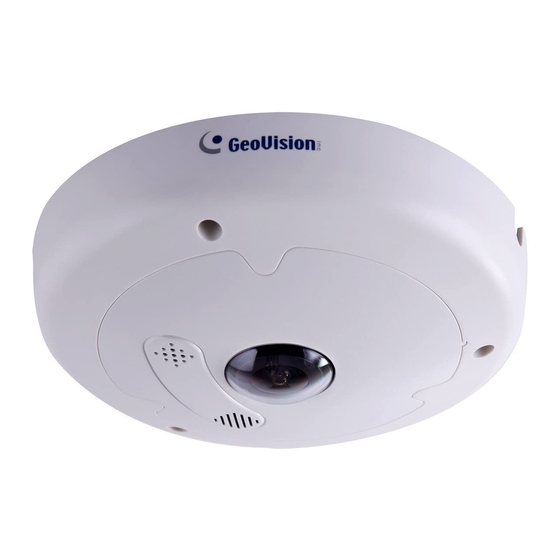
GV-Fisheye IP Camera
Thank you for purchasing GV-Fisheye IP Camera. This guide is designed to
assist the new user in getting immediate results from the GV-Fisheye IP
Camera. For advanced information on how to use the GV-Fisheye IP Camera,
please refer to GV-Fisheye IP Camera User's Manual online.
© 2015 GeoVision Inc. All rights reserved.
FE-QG-I
Advertisement
Table of Contents

Related Manuals for GeoVision GV-Fisheye


Summary of Contents for GeoVision GV-Fisheye
-
Page 1: Quick Start Guide
Quick Start Guide GV-Fisheye IP Camera Thank you for purchasing GV-Fisheye IP Camera. This guide is designed to assist the new user in getting immediate results from the GV-Fisheye IP Camera. For advanced information on how to use the GV-Fisheye IP Camera, please refer to GV-Fisheye IP Camera User's Manual online. - Page 2 GeoVision. Every effort has been made to ensure that the information in this manual is accurate. GeoVision, Inc. makes no expressed or implied warranty of any kind and assumes no responsibility for errors or omissions. No liability is assumed for incidental or consequential damages arising from the use of the information or products contained herein.
-
Page 3: Table Of Contents
3.3 GV-FE2302 / 3402 / 3403 / 5302 / 5303..............22 3.4 Connecting PoE Converter and IR LED Ring for GV-FE3403 / 5303 ....23 3.5 GV-FER3402 / 3403 / 5302 / 5303................25 4. Accessing the GV-Fisheye Camera..........27 4.1 Web Browser ......................27 4.2 Looking Up the Dynamic IP Address..............28 4.3 Configuring the IP Address ...................30... - Page 4 5. The Web Interface................. 35 5.1 Fisheye View ......................37 6. Upgrading System Firmware ............40 7. Restoring to Factory Default............41 7.1 Using the Web Interface ..................41 7.2 Directly on the Camera ..................42...
-
Page 5: Naming And Definition
Naming and Definition GeoVision Analog and Digital Video Recording Software. The GV-System GV-System also refers to Multicam System, GV-NVR System, GV-Hybrid DVR System and GV-DVR System at the same time. GV-VMS GeoVision Video Management System for IP cameras. -
Page 6: Note For Connecting To Gv-System / Gv-Vms
Note the following when the camera is connected to GV-System / GV-VMS: 1. By default, the images are recorded to the memory card inserted in the GV-Fisheye IP Camera. 2. Once the camera is connected to the GV-System / GV-VMS, the resolution set on the GV-System / GV-VMS will override the resolution set on the camera’s Web interface. -
Page 7: Note For Recording
Note for Recording 1. By default, the images are recorded to the memory card inserted in the GV-Fisheye IP Camera. Make sure the Write recording data into local storage option is enabled. If this option is disabled, the camera will stop recording to the memory card while the live view is accessed through Web browsers or other applications. -
Page 8: Note For Usb Storage And Wifi Adapter
Note for USB Storage and WiFi Adapter Mind the following limitations and requirements for using USB storage and GV-WiFi Adapter: 1. The USB hard drive must be of 2.5’’ or 3.5’’, version 2.0 or above. 2. The USB hard drive’s storage capacity must not exceed 2TB. 3. -
Page 9: Note For Installing Camera Outdoor
Note for Installing Camera Outdoor When installing GV-FER outdoor models, be sure that: 1. The camera is set up above the junction box to prevent water from entering the camera along the cables. 2. Any PoE, power, audio and I/O cables are waterproofed using waterproof silicon rubber or the like. - Page 10 4. An operating IR LED ring may reach high temperatures of up to 60°C (140°F). Disconnect the power supply and allow the IR LED ring to cool down before handling the device. 5. The silica gel bag loses it effectiveness when the dry camera is opened. To prevent the lens from fogging up, use the supplied adhesive tap and replace the silica gel bag every time you open the camera, and conceal the gel bag in camera within 2 minutes of exposing to open air.
-
Page 11: Optional Accessories
Optional Accessories Optional devices can expand the capabilities and versatility of your GV-Fisheye Camera. Contact your dealer for more information. Name Details GV-PA191 The GV-PA191 is a Power over Ethernet (PoE) adapter designed to provide power to the IP device through a single Power over Ethernet (PoE) Ethernet cable. -
Page 12: Introduction
1. Introduction Welcome to the GV-Fisheye IP Camera Quick Start Guide. In the following sections, you will learn the basic installations and configurations of the GV-Fisheye IP Cameras listed below. For a detailed user manual, see the GV-Fisheye IP Camera User’s Manual on the GV-Fisheye IP Camera Software DVD. -
Page 13: Packing List
3-Pin or 2-Pin Terminal Block Cable Connector DC 12V Power Adapter Silica Gel Bag and Adhesive Tape x 2 • • GV-IPCAM H.264 Software DVD GV-NVR Software DVD • • GV-Fisheye IP Camera Quick Start Guide GV-NVR Quick Start Guide... - Page 14 GV-FE2302 / 3402 / 5302 and GV-FE3403 / 5303 • • Fisheye Camera Support Bracket x 3 • • Camera Cover (Hard Ceiling Mount) Camera Cover (In-Ceiling Mount) • • Screw (Hard Ceiling Mount) x 3 Screw (In-Ceiling Mount) x 3 •...
- Page 15 (GV-FE3403 / 5303 only) • Installation Sticker • Power Adapter • GV-IPCAM H.264 Software DVD • GV-Fisheye IP Dome Hardware Installation Guide • GV-NVR Software DVD • GV-NVR Quick Start Guide Note: The power adapter can be excluded upon request.
- Page 16 GV-FER3402 / 5302 and GV-FER3403 / 5303 • • Fisheye Camera Support Bracket x 3 • • Camera Cover (Hard Ceiling Mount) Camera Cover (In-Ceiling Mount) • • Screw (Hard Ceiling Mount) x 3 Screw (In-Ceiling Mount) x 3 • •...
- Page 17 • Cable Connector • Power Adapter (DV 12V, 1.25A) • GV-NVR Software DVD • GV-IPCAM H.264 Software DVD • GV-NVR Quick Start Guide • GV-Fisheye IP Dome Hardware Installation Guide Note: The power adapter (DC 12V, 1.25A) can be excluded upon request.
-
Page 18: Overview
1.2 Overview GV-FE421 / 521 / 2301 / 4301 and GV-FER521 To access the Default button, LED indicators and micro SD card slot, unscrew the screws indicated below and then remove the camera cover. GV-FE2301 / 421 / 4301 / 521. GV-FER521 GV-FER521 You can now access the Load Default button, LED indicators, and the micro SD card slot. - Page 19 GV-FER521: Name Function Lens Receives image inputs. Speaker Talks to the surveillance area from the local computer. Microphone Receives the sound from the camera. Resets all configurations to default factory settings. See 7. Default Button Restoring to Factory Default in the Quick Start Guide. Inserts a micro SD / SDHC memory card to store recorded Micro SD Card Slot data.
- Page 20 GV-FE2302 / 3402 / 3403 / 5302 / 5303 Name Function Lens Receives image inputs. Speaker Talks to the surveillance area from the local computer. Microphone Receives the sound from the camera. Status LED Indicates whether the device is booted successfully or not. LAN / PoE Connects to a 10/100 Ethernet or PoE.
- Page 21 GV-FER3402 / 3403 / 5302 / 5303 Name Function Lens Receives image inputs. Speaker Talks to the surveillance area from the local computer. Microphone Receives the sound from the camera. LEDs See the LED Indicators section below for details. Resets all configurations to default factory settings. See 7. Default Button Restoring to Factory Default in the Quick Start Guide.
-
Page 22: Installation
2. Installation The fisheye camera is designed to be mounted on the ceiling, wall or ground. There are two ways to mount the camera on the ceiling, Hard Ceiling Mount and In-Ceiling Mount. Make sure the ceiling has enough strength to support the fisheye camera. Note: To re-focus your camera, follow the instruction below. -
Page 23: Hard Ceiling Mount
To install GV-Fisheye Camera with PoE converter (GV-FE3403 / 5303), drill the 3 holes and the rectangle block indicated as “PoE Converter”; to install GV-Fisheye Camera only with the IR LED ring (GV-FE3403 / 5303 and GV-FER3403 / 5303), drill the 3 holes indicated as “Device”... - Page 24 4. Secure the fisheye camera with the 3 hard ceiling mount screws provided. 5. For outdoor GV-Fisheye Cameras (GV-FER3402 / 3403 / 521 / 5302 / 5303), install the supplied cable connector to waterproof the cable. You should have 2 components: Prepare an internet cable with the RJ-45 connector on one end only.
- Page 25 (for hard ceiling mount) on top of the camera and tighten the screws with the supplied torx wrench. 7. For GV-Fisheye Camera with an IR LED ring, follow the steps below to secure the IR LED ring to the camera.
-
Page 26: In-Ceiling Mount
2.2 In-Ceiling Mount In-Ceiling Mount allows the GV-Fisheye IP Camera to be mounted into the ceiling, revealing a small portion of the camera. In-Ceiling Mount requires the ceiling board to be between 0.5 – 3.0 cm (0.2 – 1.18 in). - Page 27 2. Align the 3 support brackets with the holes on the back of the camera and secure using the in-ceiling mount screws provided. 3. For outdoor GV-Fisheye Cameras (GV-FER3402 / 521 / 5302), install the supplied cable connector to waterproof the cable. See to step 5 in 2.1 Hard Ceiling Mount for details.
- Page 28 6. From the front side of the camera, tighten the screws. 7. Connect the camera with power, network and other wires. For details, see 3. Connecting the Camera. 8. Place the camera cover for in-ceiling mount on top of the camera and tighten the 3 screws or just put on the in-ceiling cover if it does not contain screws.
-
Page 29: Wall Mount And Ground Mount
2.3 Wall Mount and Ground Mount To mount the camera on a wall, follow the instructions in 2.1 Hard Ceiling Mount. For ground mount, simply place the camera on a flat surface such as a conference table. Hint: Mount the fisheye camera in the middle of the wall to have an excellent overview. -
Page 30: Connecting The Camera
Black Connecting to Power You can use a Power over Ethernet (PoE) adaptor to connect the GV-Fisheye IP Camera on the network, and the power will be provided over the network cable. Alternatively, you can use a standard network cable to connect the camera to your network, and then follow the steps... - Page 31 1. Insert the yellow wire to the pin on the right-side of the terminal block and the orange wire to the pin on the left-side of the terminal block. 2. Use a small flat-tip screwdriver to secure the screws above the pins. 3.
-
Page 32: Gv-Fer521
The GV-FER521 comes with a PoE cable that allows you to connect to the power and network through a PoE adaptor. See “Power over Ethernet” in Specifications, GV-Fisheye IP Camera User’s Manual on the GV-Fisheye IP Camera Software DVD before purchasing a PoE adapter. -
Page 33: Gv-Fe2302 / 3402 / 3403 / 5302 / 5303
Power over Ethernet (PoE): connect the camera to a PoE switch with a standard network cable to supply power and network. PoE Converter: this method is only applicable to indoor GV-Fisheye Camera installed with an IR LED ring (GV-FE3403 / 5303). A PoE converter allows the camera to be connected to a PoE switch (thus supplied with network and power over a network cable), and also supplies power to IR LED ring. -
Page 34: Connecting Poe Converter And Ir Led Ring For Gv-Fe3403 / 5303
3.4 Connecting PoE Converter and IR LED Ring for GV-FE3403 / 5303 To install a PoE converter, follow the steps below. Note: Instead of installing the PoE converter, you can connect the camera to a PoE switch and the IR LED ring with a power adapter separately. Connect the PoE converter to a PoE switch with a standard network cable. - Page 35 IMPORTANT: It is advised to shorten the IR LED ring’s wire to approximately 20 cm for it to fit inside the PoE converter. 20cm Secure the camera to the PoE converter with the supplied screws. Secure the PoE converter to the ceiling with 3 self-prepared screws.
-
Page 36: Gv-Fer3402 / 3403 / 5302 / 5303
3.5 GV-FER3402 / 3403 / 5302 / 5303 Camera's data cable Remove the camera cover with the supplied torx wrench. Supply power to the camera with one of the following: A. Power adapter: see Assembling the Power Adapter later in this section. B. - Page 37 Assembling the Power Adapter Insert the supplied power cable into the supplied waterproof rubber. Insert the power cable into the supplied female terminal block as illustrated and plug it into the terminal block connector in the camera. Insert the power wires at the other end into the male terminal block as illustrated and plug it to the power adapter.
-
Page 38: Accessing The Gv-Fisheye Camera
4. Accessing the GV-Fisheye Camera 4.1 Web Browser Once installed, your GV-Fisheye IP Camera is accessible over the network. Make sure your PC has good network connection. The supported Web browsers are Microsoft Internet Explorer 7.x or later, Firefox, Google Chrome, Safari. -
Page 39: Looking Up The Dynamic Ip Address
4.2 Looking Up the Dynamic IP Address By default, when GV-Fisheye Camera is connected to LAN with a DHCP server, it is automatically assigned with a dynamic IP address. Follow the steps below to look up this IP address. Note: GV-Fisheye Camera has a default IP address 192.168.0.10, and the login ID and... - Page 40 4. The login page appears. 5. Type the default ID and password admin and click Apply to login.
-
Page 41: Configuring The Ip Address
Note: If your camera is assigned with the default IP address 192.168.0.10, it is advisable to change this IP address to avoid IP conflict with other GeoVision IP devices. 1. In the left menu, select Network and then LAN to begin the network settings. - Page 42 LAN, use the GV-IP Device Utility to look up its current dynamic IP address. See Checking the Dynamic IP Address, Chapter 2, GV-Fisheye IP Camera User's Manual. If your camera uses a public dynamic IP address via PPPoE, use the Dynamic DNS service to obtain a domain name linked to the camera’s changing IP address first.
-
Page 43: Configuring The Wireless Connection
4.4 Configuring the Wireless Connection Follow the steps below to set up wireless connection to your GV-Fisheye Camera (GV-FE2302 / 3402 / 3403 / 5302 / 5303 only). 1. To set up the wireless LAN for the first time, power on the camera, connect a standard network cable and insert a WiFi adapter. - Page 44 GV IP Device Utility to search for the device. 4. For detailed information on configuring the wireless LAN, see Wireless Client Mode, Administrator Chapter, GV-Fisheye User Manual on the Software DVD. 4. Enable wireless LAN. On the Web interface, select Network and LAN. This page appears.
- Page 45 To use a dynamic IP address assigned by the DHCP server, select Dynamic IP address. To use a fixed IP address, select Static IP address and type the IP address information. 5. Click Apply. The Camera will start creating a wireless connection to the access point. 6.
-
Page 46: The Web Interface
5. The Web Interface 1 2 3 4 5 6 7 No. Name Function Play Plays live video. Stop Stops playing video. Listens to the audio around the camera. Microphone Speaker Talks to the surveillance area from the local computer. Snapshot Takes a snapshot of live video. - Page 47 No. Name Function Brings up these functions: Alarm Notify, Video and Audio Show System Configuration, Remote Config, Show Camera Name and Image Menu Enhance. Displays the camera information, video settings, audio data rate, I/O device status, images captured upon alarm, and GPS location of the Control Panel camera.
-
Page 48: Fisheye View
5.1 Fisheye View To enable the fisheye options, right-click the live view image and select Geo Fisheye. Right-click the image again and select Fisheye Option to see the following options. Image Alignment: By default, the image should be properly aligned already. If not, follow the steps below to align the image for each model: GV-FE2302 / 3402 / 3403 / 5302 / 5303 and GV-FER3402 / 3403 / 5302 / 5303: Align the circle with the outer edge of the camera image, and then align it with the inner... - Page 49 If the image is not centered, please contact your sales representative and send your device back to GeoVision for adjustment. Refer to Chapter 3, GV-Fisheye IP Camera User's Manual to see how to determine if your device needs adjustment or not.
- Page 50 Adjust AutoPan Speed At Top-Left Channel: Select low, medium, or high speed to enable Auto Pan for one PTZ view at the rotation speed of your choice. This option applies to Quad view, 360 degree and Single view. Zoom: Select Zoom In or Zoom Out and then click on the image. Show Source Video At Top-Right Channel: Shows the circular source image in the top-right quadrant when Quad view is selected.
-
Page 51: Upgrading System Firmware
6. Upgrading System Firmware GeoVision periodically releases the updated firmware on the website. To load the new firmware into the GV-Fisheye IP Camera, read the important notes and then follow the instructions below. IMPORTANT: 1. While the firmware is being updated, the power supply must not be interrupted, and do not unplug the Ethernet cable if the cable is the source of power supply (Power over Ethernet or PoE supported). -
Page 52: Restoring To Factory Default
7. Restoring to Factory Default You can restore the camera to factory default settings using the Web interface or directly on the camera. 7.1 Using the Web Interface 1. In the left menu, select Management and select Tools. 2. Under the System Settings section, click the Load Default button. -
Page 53: Directly On The Camera
7.2 Directly on the Camera 1. Use the supplied torx wrench to remove the camera cover. 2. Use a pointy object such as the tip of a pen to hold down the Load default button labeled below. GV-FER521 GV-FE2302 / 3402 / 3403 / 5302 / 5303 System Status LED Default button... - Page 54 FER3402 / 3403 / 5302 / 5303 3. Release the default button when the system status LED blinks. 4. When the status LED fades, the process of loading default settings is completed and the camera reboots automatically.
Need help?
Do you have a question about the GV-Fisheye and is the answer not in the manual?
Questions and answers