Table of Contents
Advertisement
Quick Links
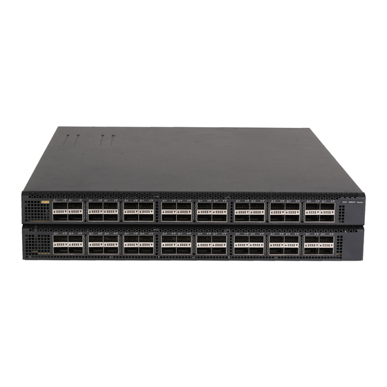
H3C S9820 Switch Series
Troubleshooting Guide
Document version: 6W100-20190815
Copyright © 2019 New H3C Technologies Co., Ltd. All rights reserved.
No part of this manual may be reproduced or transmitted in any form or by any means without prior written consent of New
H3C Technologies Co., Ltd.
Except for the trademarks of New H3C Technologies Co., Ltd., any trademarks that may be mentioned in this document are
the property of their respective owners.
The information in this document is subject to change without notice
Advertisement
Table of Contents
Troubleshooting

Related Manuals for H3C S9820 Series


Summary of Contents for H3C S9820 Series
- Page 1 No part of this manual may be reproduced or transmitted in any form or by any means without prior written consent of New H3C Technologies Co., Ltd. Except for the trademarks of New H3C Technologies Co., Ltd., any trademarks that may be mentioned in this document are the property of their respective owners.
-
Page 2: Table Of Contents
A QSFP28 fiber port fails to come up ··························································································· 20 Symptom ························································································································· 20 Troubleshooting flowchart ··································································································· 21 Solution ··························································································································· 21 Non-H3C transceiver module error message ················································································· 22 Symptom ························································································································· 22 Troubleshooting flowchart ··································································································· 23 Solution ··························································································································· 23 ... - Page 3 Symptom ························································································································· 24 Troubleshooting flowchart ··································································································· 24 Solution ··························································································································· 24 Error frames (for example, CRC errors) on a port ············································································ 25 Symptom ························································································································· 25 Troubleshooting flowchart ··································································································· 26 Solution ··························································································································· 26 Failure to receive packets ·········································································································· 27 ...
-
Page 4: Introduction
Introduction This document provides information about troubleshooting common software and hardware problems with the S9820 switch series. This document is not restricted to specific software or hardware versions. General guidelines IMPORTANT: To prevent a problem from causing loss of configuration, save the configuration each time you finish configuring a feature. -
Page 5: Collecting Log And Operating Information
Collecting log and operating information IMPORTANT: To facilitate quick troubleshooting, execute the following commands: • info-center enable—Enables the information center. By default, the information center is enabled. • info-center logfile enable—Enables the log file feature so the system outputs logs to log files. By default, the log file feature is enabled. -
Page 6: Collecting Diagnostic Log Messages
<Sysname> logfile save The contents in the log file buffer have been saved to the file flash:/logfile/logfile.log Identify the common log file on each member device: # Display the common log file on the master device. <Sysname> dir flash:/logfile/ Directory of flash:/logfile 0 -rw- 21863 Jul 11 2013 16:00:37 logfile.log... -
Page 7: Collecting Operating Statistics
Collecting operating statistics You can collect operating statistics by saving the statistics to a file or displaying the statistics on the screen. When you collect operating statistics, follow these guidelines: • Log in to the device through a network or management port instead of the console port, if possible. -
Page 8: Troubleshooting Hardware
Decompressing file flash:/diag_Sysname_20160101-000704.gz..Done. Display the content of the operating statistics file. <Sysname> more diag_Sysname_20160101-000704 =============================================== ===============display clock=============== 23:49:53 UTC Tue 01/01/2016 ================================================= ---- More ---- Troubleshooting hardware This section provides troubleshooting information for common hardware problems. NOTE: This section describes how to troubleshoot unexpected switch reboot, power module failure, and fan tray failure. -
Page 9: Troubleshooting Flowchart
Troubleshooting flowchart Figure 1 Troubleshooting unexpected switch reboot Unexpected switch reboot Can you access the CLI? Collect operating Reload the system Is the system software information software image image correct? Resolved? Contact the support Solution To resolve the problem: Verify that you can access the CLI after the switch reboots. If you can access the CLI, execute the display diagnostic-information command to collect operating information. -
Page 10: Operating Power Module Failure
Use the BootWare menu to reload the system software image. b. Configure it as the current system software image. If the problem persists, contact H3C Support. Operating power module failure Symptom A trap or log is generated indicating that an operating power module is faulty. -
Page 11: Newly Installed Power Module Failure
Normal state in the new slot. If the power module remains in Fault state, go to step 4. If the problem persists, contact H3C Support. Fan tray failure Symptom A trap or log indicates that a fan tray is faulty, or the display fan command shows that a fan tray is not in Normal state. -
Page 12: Solution
If a new fan tray is not readily available, power off the switch to avoid damage caused by high temperature. If the problem persists, contact H3C Support. Related commands This section lists the commands that you might use for troubleshooting the hardware. -
Page 13: Troubleshooting Acl
If this field displays 0, the ACL hardware resources are exhausted. To free hardware resources, delete unnecessary ACLs. If the problem persists, contact H3C Support. ACL application failure without an error message Symptom The system applies a packet filter or an ACL-based QoS policy to the hardware. However, the ACL... -
Page 14: Troubleshooting Flowchart
Troubleshooting flowchart Figure 2 Troubleshooting ACL application failure Solution Choose a solution depending on the module that uses the ACL. ACL used in a QoS policy To resolve the problem when the ACL is used in a QoS policy: Verify that the QoS policy is configured correctly: a. -
Page 15: Related Commands
If the ACL is configured incorrectly, reconfigure it. If the ACL is configured correctly, go to step 3. If the problem persists, contact H3C Support. ACL used in a packet filter To resolve the problem when the ACL is used in a packet filter: Verify that the packet filter is configured correctly. -
Page 16: Troubleshooting Irf
Command Description display acl Displays configuration and match statistics for ACLs. Displays operating statistics for multiple feature modules in the display diagnostic-information system. Displays whether an ACL has been successfully applied to an display packet-filter interface for packet filtering. display qos-acl resource Displays QoS and ACL resource usage. -
Page 17: Troubleshooting Flowchart
Troubleshooting flowchart Figure 3 Troubleshooting IRF fabric setup failure IRF setup failure You cannot add additional devices to the Number of members fewer IRF fabric or complete than the upper limit? IRF merge Assign a unique member Member ID unique? ID to each member Resolved? device... -
Page 18: Solution
Solution To resolve the problem: Verify that the number of member devices does not exceed the upper limit (10). If you are adding a new member device to an existing IRF fabric or merging IRF fabrics, use the display irf command to identify the number of member devices in the IRF fabrics. If the total number of member devices exceeds the upper limit, the IRF setup will fail. - Page 19 Enabling status of packet loss prevention for OpenFlow forwarding (set by using the openflow lossless enable command). VXLAN hardware resource allocation mode (set by using the hardware-resource vxlan command). If the problem persists, contact H3C Support.
-
Page 20: Related Commands
Related commands This section lists the commands that you might use for troubleshooting IRF. Command Description Displays IRF fabric information, including the member ID, role, priority, display irf bridge MAC address, and description of each IRF member. Displays basic IRF settings, including the current member ID, new display irf configuration member ID, and physical interfaces bound to the IRF ports on each IRF member device. -
Page 21: Troubleshooting Flowchart
Troubleshooting flowchart Figure 4 Troubleshooting link aggregation failure Solution To resolve the problem: Verify that all physical connections are correct. You can verify the physical connections against your network plan. Verify that all member ports are up:... -
Page 22: Related Commands
a. Execute the display interface command to display the status of the member ports. b. If the member ports are down, follow the solution in "Troubleshooting ports" to troubleshoot the problem. Verify that the member ports have the same operational key and attribute configurations as the reference port: a. -
Page 23: Troubleshooting Ports
Commands Description display current-configuration interface Displays interface configuration. display interface Displays Ethernet interface information. Display detailed information about display link-aggregation verbose aggregation groups that correspond to the existing aggregate interfaces. Configure the maximum number of Selected link-aggregation selected-port maximum ports allowed in an aggregation group. Troubleshooting ports This section provides troubleshooting information for common port problems. -
Page 24: Troubleshooting Flowchart
Troubleshooting flowchart Figure 5 Troubleshooting link up failure on a QSFP28 fiber port A port failed to come up Speed/duplex match Configure matching Resolved? on local and peer port? speed/duplex Speed/duplex Configure matching match on transceiver module and Resolved? speed/duplex port? Local/peer port Replace local/peer port... -
Page 25: Non-H3C Transceiver Module Error Message
For more information about fibers, see the installation guide for the switch. If the problem persists, contact H3C Support. Non-H3C transceiver module error message Symptom The output from the display logbuffer command shows that the transceiver module is not an H3C transceiver module. -
Page 26: Troubleshooting Flowchart
: H3C Ordering Name : QSFP-40G-LR4-WDM1300 If the vendor name field does not display H3C, replace the transceiver module with an H3C transceiver module. If the vendor name field displays H3C, perform the following tasks: − Execute the display hardware internal transceiver register interface command in... -
Page 27: Transceiver Module Does Not Support Digital Diagnosis
− Provide the information to H3C Support to verify that the transceiver module is an H3C transceiver module. If it is not, replace it with an H3C transceiver module. If the problem persists, contact H3C Support. Transceiver module does not support digital... -
Page 28: Error Frames (For Example, Crc Errors) On A Port
− Execute the display transceiver manuinfo interface command to save the transceiver module information. − Provide the information to H3C Support to verify that the transceiver module is an H3C transceiver module. If the module is not from H3C, replace it with an H3C transceiver module. -
Page 29: Troubleshooting Flowchart
Troubleshooting flowchart Figure 8 Troubleshooting error frames (for example, CRC errors) on a port Solution To resolve the problem: Examine the error frame statistics and identify the error frame type: a. (Optional.) Use the reset counter interface command in user view to clear the packet statistics of the port. -
Page 30: Failure To Receive Packets
Verify that the incoming traffic and outgoing traffic have not exceeded the maximum traffic processing capability of the local device and the peer device. If the problem persists, contact H3C Support. Failure to receive packets Symptom... -
Page 31: Troubleshooting Flowchart
Troubleshooting flowchart Figure 9 Troubleshooting failure to receive packets Solution To resolve the problem: Verify that the ports at both ends are up. Examine the packet statistics of the port: a. (Optional.) Use the reset counter interface command to clear the packet statistics of the port. -
Page 32: Failure To Send Packets
If the port is a fiber port, replace the transceiver module in the port. If the port can receive packets, troubleshoot the remaining possible points of failure on the transmission path. The troubleshooting process is beyond the scope of this document. If the problem persists, contact H3C Support. Failure to send packets Symptom... -
Page 33: Troubleshooting Flowchart
Troubleshooting flowchart Figure 10 Troubleshooting failure to send packets A port failed to send packets Display packet statistics for the port Port configuration Modify port Problem resolved? affects packet receiving? configuration Port and link Use the correct port Problem resolved? medium correct? and link medium Contact the support... -
Page 34: Related Commands
If the port can send packets, troubleshoot the remaining possible points of failure on the transmission path. The troubleshooting process is beyond the scope of this document. If the problem persists, contact H3C Support. Related commands This section lists the commands that you might use for troubleshooting ports. -
Page 35: Troubleshooting Evpn
Command Description Displays electronic label information for the transceiver display transceiver manuinfo interface module in an interface. Troubleshooting EVPN This section provides troubleshooting information for common problems with EVPN. EBGP or IBGP neighbor relationship setup failure Symptom Two devices cannot set up an EBGP or IBGP neighbor relationship. Troubleshooting flowchart Figure 11 Troubleshooting EBGP or IBGP neighbor relationship setup failure BGP neighbor... -
Page 36: Solution
Solution To resolve the problem: Verify that BGP is correctly configured: a. Execute the display bgp peer l2vpn evpn command on the devices to view their BGP settings. b. Verify that the EBGP or IBGP peers on the devices have matching AS numbers. If the AS numbers do not match, use the peer as-number command to modify the AS numbers. -
Page 37: Troubleshooting System Management
Command Description display bgp l2vpn evpn Displays BGP EVPN routes. display bgp peer l2vpn evpn Displays BGP peer or peer group information for EVPN. Displays information about peers that are automatically display evpn auto-discovery discovered through BGP. debugging bgp event Enables BGP event debugging. -
Page 38: Solution
Solution To resolve the problem: Identify the job that has a high CPU utilization. <Sysname> system-view [Sysname] probe [Sysname-probe] display process cpu slot 1 CPU utilization in 5 secs: 3.7%; 1 min: 3.1%; 5 mins: 3.8% 5Sec 1Min 5Min Name 0.0% 0.0% 0.0%... -
Page 39: High Memory Utilization
Kernel stack: [<80480754>] schedule+0x954/0x1250 [<8028f720>] watchdog+0xb0/0x410 [<802656d0>] kthread+0x130/0x140 [<8021d730>] kernel_thread_helper+0x10/0x20 Iteration 3 of 5 ------------------------------ Kernel stack: [<80480754>] schedule+0x954/0x1250 [<8028f720>] watchdog+0xb0/0x410 [<802656d0>] kthread+0x130/0x140 [<8021d730>] kernel_thread_helper+0x10/0x20 Iteration 4 of 5 ------------------------------ Kernel stack: [<80480754>] schedule+0x954/0x1250 [<8028f720>] watchdog+0xb0/0x410 [<802656d0>] kthread+0x130/0x140 [<8021d730>] kernel_thread_helper+0x10/0x20 Iteration 5 of 5 ------------------------------ Kernel stack:... -
Page 40: Troubleshooting Flowchart
Troubleshooting flowchart Figure 13 Troubleshooting high memory utilization Solution To resolve the problem: Execute the display system internal kernel memory pool command multiple times to display memory usage information. <Sysname> system-view [Sysname] probe [Sysname-probe] display system internal kernel memory pool slot 1 Active Number Size... -
Page 41: Related Commands
L2VFIB_LpwEntryCacheName(1) ---- More ---- Each value line shows the memory information for a slab. The Number field shows the number of objects (memory blocks) allocated to the module. The Active field shows the number of objects used. If the percentage of the used objects keeps increasing, the slab might have memory leakage problems. -
Page 42: Troubleshooting Flowchart
Troubleshooting flowchart Figure 14 Troubleshooting Layer 2 packet loss failure Solution To resolve the problem: Verify that no error packets have been received on the local port: a. Execute the display interface command and check for error packets. <Sysname>display interface hundredgige 1/0/32 HundredGigE1/0/32 current state: UP Line protocol state: UP IP Packet Frame Type: PKTFMT_ETHNT_2, Hardware Address: 000f-e200-002b... - Page 43 # Use the probe command to enter probe view. In probe view, execute the debug port mapping command to identify the chip port with which the interface is associated. [H3C-probe]debug port mapping slot 1 [Interface] [Unit] [Port] [Name] [Combo?] [Active?] [IfIndex] [MID] [Link]...
- Page 44 HGE1/0/5 ce20 down HGE1/0/6 ce21 0x12 down HGE1/0/7 ce22 0x13 down HGE1/0/8 ce23 0x18 down HGE1/0/9 ce24 0x19 down HGE1/0/10 ce25 0x1e down HGE1/0/11 ce26 0x1f down HGE1/0/12 ce27 0x24 down HGE1/0/13 ce28 0x25 down HGE1/0/14 ce29 0x2a down HGE1/0/15 ce30 0x2b down...
- Page 45 HGE1/0/29 ce44 0x55 down HGE1/0/30 ce45 0x5a down HGE1/0/31 ce46 0x5b down HGE1/0/32 ce47 0x60 down HGE1/0/33 0x61 down HGE1/0/34 0x66 down HGE1/0/35 0x67 down HGE1/0/36 0x6c down HGE1/0/37 0x6d down HGE1/0/38 0x72 down HGE1/0/39 0x73 down HGE1/0/40 0x78 down HGE1/0/41 0x79 down...
- Page 46 HGE1/0/53 ce52 0x9d down HGE1/0/54 ce53 0xa2 down HGE1/0/55 ce54 0xa3 down HGE1/0/56 ce55 0xa8 down HGE1/0/57 ce56 0xa9 down HGE1/0/58 ce57 0xae down HGE1/0/59 ce58 0xaf down HGE1/0/60 ce59 0xb4 down HGE1/0/61 ce60 0xb5 down HGE1/0/62 ce61 0xba down HGE1/0/63 ce62 0xbb...
- Page 47 PERQ_BYTE(3).xe0 2,741,472 +2,741,472 330/s Verify that packets are not mistakenly filtered out by ACLs: a. Examine the ACL and QoS policy configurations for packet filtering on the port, on the VLAN of the port, or globally. If packets are mistakenly filtered out, modify the ACL or QoS policy configuration.
-
Page 48: Related Commands
− If the state of the port is DOWN, locate the reason for the port to be down. The possible reasons include: its uplink device is configured with monitor link, the link of the port fails, or the port is shut down. Further troubleshoot the problem based on the reason for the port to be down. -
Page 49: Layer 3 Forwarding Failure
Command Description Displays whether an ACL has been successfully applied to an display packet-filter interface for packet filtering. display portal interface Displays portal configuration and portal running state on an interface. Displays the rate limit configuration and statistics on a specified display qos lr interface interface or all the interfaces. -
Page 50: Troubleshooting Flowchart
Troubleshooting flowchart Figure 15 Troubleshooting Layer 3 forwarding failure Packet loss at Layer 3 Troubleshoot the The port is faulty? Resolved? port ARP or ND entries Troubleshoot ARP Resolved? are correct? or ND entries Troubleshoot route Resolved? Route entries are correct? entries Contact the support Solution... -
Page 51: Related Commands
− If incorrect ND entries exist, execute the debugging ipv6 icmp command to locate the problem. − If the switch learns no ND entries, execute the ipv6 neighbor command to configure static ND entries. b. Execute the display mac-address command to verify that the output interfaces in the MAC address entries and ND entries are the same. -
Page 52: Troubleshooting Flowchart
Troubleshooting flowchart Figure 16 Troubleshooting protocol flapping Layer 3 protocol flapping Troubleshoot the Layer 2 packet loss occurs? Resolved? problem Troubleshoot the Layer 3 packet loss occurs? Resolved? problem Software-related Collect diagnostic packet loss occurs? information Contact the support Solution To resolve the problem: Verify that Layer 2 is operating correctly, as described in "Layer 2 forwarding... - Page 53 If the problem persists, contact Hewlett Packard Enterprise Support. When you contact Hewlett Packard Enterprise Support, provide diagnostic information if software-related packet loss occurred.
Need help?
Do you have a question about the S9820 Series and is the answer not in the manual?
Questions and answers