Table of Contents
Advertisement
Quick Links
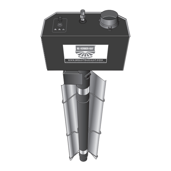
Brant Radiant Heaters, Ltd.
DX3L Series
Gas-Fired Infrared Tube Heater
WARNING: Improper installation, adjustment, alteration, service or
maintenance can cause property damage, injury or death. Read the
installation, operating and maintenance instructions thoroughly before
installing or servicing this equipment.
AVERTISSEMENT: Une installation, un réglage, une modification, une
réparation ou un entretien incorrect peut entraîner des dommages matériel,
des blessures ou la mort. lisez attentivement les instructions d'installation,
de fonctionnement et d'entretien avant de procéder à l'installation ou à
l'entretien de cet équipement.
This heater must be installed and serviced by trained gas installation and service personnel only.
Failure to comply could result in personal injury, asphyxiation, death, fire or property damage.
In locations used for the storage of combustible materials, signs must be posted to specify the
maximum permissible stacking height to maintain the required clearances from the heater to the
combustibles. Signs must either be posted adjacent to the heater thermostats or in the absence
of such thermostats, in a conspicuous location.
Not for residential use! Do not use this heater in the home, sleeping quarters, attached
garages, etc. Installation of a commercial tube heater system in residential indoor spaces
may result in property damage, serious injury, asphyxiation or death.
Cet appareil de chauffage doit être installé et entretenu par l'installation à gaz formée et le personnel de
service seulement. L'échec de se soumettre pourrait aboutir à la blessure personnelle, l'asphyxie, la mort, le
feu ou des dégâts de propriété.
Dans des emplacements utilisés pour le stockage de matériels combustibles, les signes doivent être postés
pour spécifier la hauteur d'entassement permise maximale pour maintenir les dégagements exigés de
l'appareil de chauffage au combustibles. Les signes doivent ou être postés adjacents aux thermostats
d'appareil de chauffage ou en absence de tels thermostats, dans un emplacement remarquable.
Pas pour utilisation résidentielle! N'utilisez pas cet appareil de chauffage dans la maison, des chambres
à coucher, des garages attachés, etc. L'installation d'un système d'appareil de chauffage de tube
commercial dans des espaces intérieurs résidentiels peut aboutir aux dégâts de propriété, la
blessure grave, l'asphyxie ou la mort.
For Your Safety
If you smell gas:
• Open windows.
• Do not touch electrical switches.
• Extinguish any open flame.
• Do not try to light any appliances.
• Immediately call your gas supplier from a
neighbours phone.
INSTALLER: Present this manual to the end user.
Model#:
WARNING
!
AVERTISSEMENT
!
Keep these instructions in a clean and dry place for future reference.
Serial #:
(located on rating label)
Pour Votre Sécurité
Si vous sentez le gaz:
• Fenêtres ouvertes.
• Ne touchez pas d'échanges électriques.
• Éteignez n'importe quelle flamme ouverte.
• N'essayez pas d'éclairer d'appareils.
• Appelez immédiatement votre fournisseur de gaz
d'a les voisins téléphonent.
LIODX3L-REV-00 4-19
Advertisement
Table of Contents

Related Manuals for Brant Radiant Heaters DX3L Series


Summary of Contents for Brant Radiant Heaters DX3L Series
- Page 1 Brant Radiant Heaters, Ltd. DX3L Series Gas-Fired Infrared Tube Heater WARNING: Improper installation, adjustment, alteration, service or maintenance can cause property damage, injury or death. Read the installation, operating and maintenance instructions thoroughly before installing or servicing this equipment. AVERTISSEMENT: Une installation, un réglage, une modification, une réparation ou un entretien incorrect peut entraîner des dommages matériel,...
-
Page 3: Table Of Contents
DX3L Series Contents 1.0 Introduction ..............4 Overview . -
Page 4: Introduction
Reference last page for a list of the kit contents for your model heater. Materials not included in the heater kit contents (e.g., screws, vent material, terminals, etc.) are the responsibility of the installer. Notify your product representative or Brant Radiant Heaters Ltd. of any discrepancy or missing kit contents prior to installing unit. -
Page 5: Product Specifications
DX3L Series Introduction • Product Specifications Product Specifications Chart 1.1 • DX3L Series Specifications DX3L-20-50 Nat. or Prop. 50,000 21’-9” 13’-1” 9’ to 15’ Alum Alum DX3L-20-60 Nat. or Prop. 60,000 21’-9” 13’-1” 10’ to 15’ Alum Alum DX3L-20-75 Nat. or Prop. -
Page 6: Safety
DX3L Series Introduction • Safety Labels and Their Locations Safety Labels and Their Locations Product safety signs or labels should be replaced by the product user when they no longer are legible. Contact either your local distributor or the product manufacturer for obtaining replacement signs or labels. F/N: LLV3EP1 SAMPLE 120V... - Page 7 FOR INDOOR USE ANS Z83.20b - 2011 CSA - 2011 Low - Intensity Infrared Htr. MODEL /MODELE NO. INPUT BTU/H FOR USE WITH BRANT RADIANT HEATERS LIMITED SERIAL NO. 34 SCOTT AVE., PARIS, ONTARIO 0870 XXXX XXXX 0001 DX3L-40-125N 125,000 NATURAL GAS TEL: 1-519-442-7823 WWW.BRANTRADIANT.COM...
-
Page 8: Warning Symbols
DX3L Series Safety • Warning Symbols • Applications Safety WARNING This heater must be installed and serviced by a trained gas installation and service personnel only! Improper installation, adjustment, alteration, service or maintenance can cause property damage, serious injury or death. Read and understand the installation, operating and maintenance instructions thoroughly before installing or servicing this equipment. -
Page 9: Standards, Certifications And Government Regulations
DX3L Series Safety • Standards, Certifications and Government Regulations Standards, Certifications and Government Regulations Installation of this tube heater must comply with all applicable local, state and national specifications, regulations and building codes. Contact the local building inspector and/or fire marshall for guidance. In the absence of local codes, the installation must conform to the latest edition of: United States: National Fuel Gas Code, ANSI Z223.1 (NFPA 54). - Page 10 DX3L Series Safety • Standards, Certifications and Government Regulations Chart 2.2 • Standards and Code Installation Guidelines • Building Location Building Guidelines Location Guidelines: High Altitude Installation of this tube heater is approved, without modifications, for elevations up to 6,000 feet (1,829 m) MSL (sea level) in the United States. Contact the factory for installations above these elevations.
-
Page 11: Clearance To Combustibles
Z83.20b and CSA 2.34 require you to post a sign “specifying the maximum permissible stacking height to maintain the required clearances from the heater to the combustibles” near the heaters thermostat or in absence of such thermostats in a conspicuous location. Contact Brant Radiant Heaters Ltd. or an authorized dealer for Clearance Safety Limit Signs(P/N: BR-SIGN). - Page 12 DX3L Series Safety • Clearance to Combustibles When installing the tube heating system, the minimum clearances to combustibles for your model tube heater and system configuration must be maintained. Refer to Chart 2.1 below to determine the required distances for your model. Chart 2.1 •...
-
Page 13: Installation
DX3L Series Installation • Design Considerations and Prechecks Installation WARNING Improper installation, adjustment, alteration, service or maintenance can cause property damage, serious injury or death. Read and understand, the installation, operating and maintenance instructions thoroughly before installing or servicing this equipment. Only trained, qualified gas installation and service personnel may install or service this equipment. - Page 14 DX3L Series Installation • Design Considerations When heated, materials high in hydrocarbons (solvents, paint thinner, mineral spirits, formaldehydes, etc.) can evaporate. This may result in odors or fumes being emitted into the environment. To correct this problem, clean the area and/or introduce additional ventilation. The heaters themselves, when installed and serviced in accordance with the installation manual, do not emit foul odors into the environment.
-
Page 15: Recommended Mounting Heights And Coverages
Factory recommended mounting heights are listed as a guideline. If infrared heaters are mounted too low or too high, they may result in discomfort or lack of heat. Brant Radiant Heaters Ltd. generally recommends observing the recommended mounting heights to optimize comfort conditions. However, certain applications such as spot heating, freeze protection, outdoor patio heating or very high ceilings may result in the heaters being mounted outside of the factory recommended mounting heights. -
Page 16: Hanger Placement And Suspension
DX3L Series Installation • Hanger Placement and Suspension Hanger Placement and Suspension WARNING Improper suspension of the tube heater may result in collapse and being crushed. Always suspend from a permanent part of the building structure that can evenly support the total force and weight of the heater. - Page 17 DX3L Series Installation • Hanger Placement and Suspension Figure 3.4 • Heater Mounting Layout Suspension Point NOTE: A yellow band identifying the combustion chamber(s) is located in the middle of the tube(models 150-200 MBH). Suspension Remove paper band before starting up Point heater.
- Page 18 DX3L Series Installation • Hanger Placement and Suspension Prepare mounting surface, if necessary weld blocks, drill holes (see figure 3.5). NOTE: The burner control box and radiant tubes should be in straight alignment and level. Fasten beam clamp, screw hook or other type of suspension anchor to hanging point. Attach and close S-Hook (P/N: S-HOOK) and #1 double-loop chain (P/N: THCS) to anchor.
- Page 19 DX3L Series Installation • Hanger Placement and Suspension Figure 3.6 • U-Tube Hanger Mounting Options Single Mounting Bracket Brass Knuckles Exhaust U-Tubes can be mounted from a single suspension point U-Tubes can be mounted at a using a Single Mounting Bracket (P/N: SMB) with five 15, 30 or 45 degree angle with two S-hooks and #1 double-loop chains.
-
Page 20: Radiant Tube Assembly
DX3L Series Installation • Radiant Tube Assembly Radiant Tube Assembly To install the radiant tubes: Place tubes in hangers with the welded seam facing downward and the swaged end of the tube towards the exhaust end of the heater system (see figure 3.8). Refer to page 27 for tube installation sequence. -
Page 21: Optional Elbow Or U-Bend Accessory Configuration
DX3L Series Installation • Optional Elbow or U-Bend Accessory Configuration Slip-fit the radiant tube sections together until tightly connected (install the swaged end of each tube towards exhaust end). NOTE: If it is difficult to mate the tubes, they may be installed incorrectly. Center tube clamps over the seam where two radiant tube sections connect. - Page 22 DX3L Series Installation • Optional Elbow or U-Bend Accessory Configuration Figure 3.12 • Elbow and U-Bend Clearances Elbow can be set in both directions Dimension A Tube Clamp Tube Clamp U-Bend can be set in both directions Dimension A Tube Clamp 12”...
-
Page 23: Burner Control Box Suspension
DX3L Series Installation • Burner Control Box Suspension Burner Control Box Suspension Suspending the burner control box must be done in accordance with applicable codes listed in the Safety section and these instructions. The burner control box must be in straight alignment with all radiant tubes and level. Contact your local distributor or the factory to see if your application allows for the rotation of the burner control box. -
Page 24: Reflector Assembly
DX3L Series Installation • Reflector Assembly Reflector Assembly To install the reflectors (see figure 3.16): Attach the reflector center supports onto radiant tubes. Slide each reflector section through the hangers and adjust the reflector tension spring into the V-groove on the top of the reflector. The reflectors should overlap approximately 4 inches. To prevent the reflectors from shifting, secure the reflector sections together using sheet metal screws, except at the expansion joint (see Chart 3.6). - Page 25 DX3L Series Installation • Reflector Assembly Chart 3.5 Common Optional Accessories Reflector Accessory Description Part Number 90° bend, highly polished aluminum reflector elbow Elbow Reflector* designed to fit atop one elbow accessory fitting. 180° bend, highly polished aluminum reflector U-Reflector* U-bend designed to fit atop one U-bend accessory fitting.Reference figure 3.6 Highly polished side shield extension used to direct...
-
Page 26: Baffle Assembly And Placement
DX3L Series Installation • Baffle Assembly and Placement Baffle Assembly and Placement Different models and inputs utilize specific baffle lengths. Remove all enclosed baffle sections from box and retain with applicable heater. Reference shipping label for proper baffle size. To assemble the baffles: NOTE: Baffles may be inserted into the tube while being assembled. Determine the number of baffles needed for your model number. -
Page 27: Final Heater Assembly
DX3L Series Installation • Final Heater Assembly Final Heater Assembly Chart 3.6 Tube Installation Sequence, Baffle Location and Secured Joints for Reflectors NOTE: When securing joints on reflectors which are rotated on an angle from horizontal, secure joint only on top side of reflector to allow for sufficient heater expansion and contraction. -
Page 28: Venting
DX3L Series Installation • Venting Venting The heating system must be vented as described here to properly direct flue gases from the unit to the outside atmosphere. The venting can terminate vertically through the roof (up) or horizontally through a sidewall (sideways). - Page 29 General Venting Requirements General Venting Requirements The venting system for DX3L Series heaters may terminate horizontally through a sidewall or vertically through the roof, and may be individually or commonly vented. Configuration of the vent termination determines the category type. All model heaters must be installed in accordance to the requirements of this section, as well as the requirements of its category determination, as described in this manual.
- Page 30 DX3L Series Installation • General Venting Requirements When possible, avoid venting through an unconditioned space. Venting through an unconditioned space promotes condensation. When venting through an unconditioned space is unavoidable, or if the unit is installed in an area that is prone to condensation, insulate venting runs greater than 5 feet to minimize the production of condensation.
- Page 31 DX3L Series Installation • Vertical Venting (Category I) Figure 3.21 • Rooftop Venting - Side View Vent Cap 24 in. Min.* Roof* Storm Collar Adjustable Roof Flashing Double-Wall B Vent 1 in. Minimum Clearance - Use Attic Insulation Shield (Field Supplied) Fire Stop Spacer Heater B to C Adapter...
- Page 32 DX3L Series Installation • Horizontal Venting (Category III) Horizontal Venting (Category III) An appliance that operates with a positive vent static pressure and with a vent gas temperature that avoids excessive condensate production in the vent is said to be “Category III”. The heater is considered a Category III appliance if the venting system meets all of the following criteria: •...
- Page 33 DX3L Series • Installation • Vent Location s and Clearances Sidewall Venting Requirements Vent Locations and Clearances: • Vent must terminate a minimum of 4 feet below, 4 feet horizontally from, or 1 foot above any window or door that may be opened or gravity air inlet into the building. •...
- Page 34 • DX3L Series Installation • Common Venting (Category I) Common Rooftop Venting Common Venting (Category I) The common vent system and all attached appliances must be Category I. The vent connector should be routed in the most direct route from the units to the common vent. Where two or more vent connectors enter a common gas vent or chimney flue, the smaller connector shall enter at the highest level consistent with the available head room or clearance to combustible material.
- Page 35 DX3L Series Installation • Combustion Air Requirements Common Venting (Category III) • A staggered arrangement or a dual exhaust assembly (P/N: Y) must be used when joining two heaters to a common vent so that by-products of one heater do not flow into the adjoining vent of the other heater.
-
Page 36: Optional Unvented Operation
DX3L Series Installation • Separated Combustion Systems Optional Unvented Operation WARNING Not for residential use. The use of unvented tube heaters in residential indoor spaces may result in property damage, serious injury or death. Use unvented operation in commercial and industrial installations with proper ventilation rates only. When using an unvented configuration (commercial &... -
Page 37: Combustion Air Requirements
DX3L Series Installation • Separated Combustion Systems • Combustion Air Requirements Non-contaminated outside air for combustion must be ducted to the heater if any of the following apply: • Chemicals such as chlorinated or fluorinated hydrocarbons (typical sources are refrigerants, solvents, adhesives, degreasers, paints, paint removers, lubricants, pesticides, etc.). - Page 38 DX3L Series Installation • Combustion Air Supply • Operational Unvented Operation Chart 3.7 • Limitations for Length and Size of Combustion Air Intake Duct Single Heater Intake Dual Heater Intake Air Intake Duct Size Max. Intake Length Duct Size Max. Intake Length 4 in.
-
Page 39: Gas Supply Installation Instructions
DX3L Series Installation • Combustion Air Requirements • Gas Supply Gas Supply Installation Instructions The gas supply to the tube heater must be connected and tested in accordance with national, state, provincial, and local codes along with guidelines in this manual. In the United States refer to the latest edition of the ANSI Z223.1 (NFPA54) Standard and in Canada refer to the latest edition of the CAN/ CGA B149.1 Standard. - Page 40 The DX3L Series heater is equipped to connect to the Type 1 rubber gas connector (Included). Do not connect the main gas line directly to the heaters gas inlet without the use of the flexible connector.
- Page 41 DX3L Series Installation • Gas Supply When connecting piping to the unit, the use of a thread joint compound is required. The thread compound (pipe dope) shall be resistant to the action of liquefied petroleum gas or any other chemical constituents of the gas to be conducted through piping.
- Page 42 DX3L Series Installation • Gas Supply WARNING Testing for gas leaks with an open flame or other sources of ignition may lead to a fire or explosion and cause serious injury or death. Test in accordance with CAN/CSA codes. Figure 3.29 •...
- Page 43 DX3L Series Installation • Gas Supply Figure 3.31 • Gas Connection (Type 1 Hose Gas Connector shown) • Side View NOTE: Do not exceed 14 Inches W.C. to the appliance. Ball Valve / Inlet Tap Adapter Adapter Elbow Elbow Drip Leg/ Burner Sediment Trap Control Box...
-
Page 44: Leak Testing
DX3L Series Installation • Leak Testing Leak Testing WARNING Testing for gas leaks with an open flame or other sources of ignition may lead to a fire or explosion and cause serious injury or death. Test in accordance with NFPA or local codes. WARNING Gas pressures to the appliance controls must never exceed 14 inches W.C. -
Page 45: Electrical Requirements
DX3L Series Installation • Electrical Requirements WARNING Improper installation, adjustment, alteration, service or maintenance can cause property damage, serious injury or death. Read and understand, the installation, operating and maintenance instructions thoroughly before installing or servicing this equipment. Only trained, qualified gas installation and service personnel may install or service this equipment. Not for residential use! Do not use this heater in the home, sleeping quarters, attached garages, etc. -
Page 46: Thermostat
Use 18 gauge wire (or larger) that is suitable for a NEC Class 2 rating for thermostat connections. Each DX3L series heater requires a thermostat rated for 24 VAC to operate. The heater comes standard with a terminal strip for making the thermostatic connection, located on the back panel. -
Page 47: Wiring
DX3L Series Installation • Wiring Internal Wiring Diagrams Before wiring this appliance, check the existing wiring; replace if necessary. If any of the original wire supplied with the appliance must be replaced, it must be replaced with copper wiring material having a rating of at least 600V, 105°C. - Page 48 DX3L Series Installation • Wiring The thermostat terminal designations are as follows: R: 24 VAC Power W: Call for Heat C: Common for 24 VAC Power (if required for thermostat power) 24 VAC is supplied from an internal 40 VA transformer. DO NOT supply 24 V to the terminal strip. Figure 2.2 Single Heater, Single Thermostat Connection •...
- Page 49 DX3L Series • Installation Wiring...
-
Page 50: Unit-Start-Up (Commissioning)
DX3L Series Installation • Unit Start-up (Commissioning) • Pre-Start Up Checks Unit Start-up (Commissioning) WARNING Improper installation, adjustment, alteration, service or maintenance can cause property damage, serious injury, or death. This heater must be installed and serviced by a trained gas installation and service personnel only. -
Page 51: High Altitude Operation
DX3L Series Installation • High Altitude Operation High Altitude Operation WARNING Explosion hazard. This heater must be converted by a trained gas installation and service personnel only. Failure to comply could result in personal injury, asphyxiation, death, and fire or property damage. High altitude operation of this tube heater is approved, without modification, for elevations up to 6,000 feet (1,829 m) above MSL (sea level) in the United States. -
Page 52: Operation
DX3L Series Operation • Operating Instructions Operation WARNING This appliance does not have a pilot ignition. It is equipped with an ignition device which automatically lights the burner. Do not attempt to light the system by hand. BEFORE OPERATING, smell all around the appliance area for gas. Be sure to smell next to the floor because some gas is heavier than air and will settle to the floor. -
Page 53: Sequence Of Operation
DX3L Series Operation • Sequence of Operation WARNING This heater must be installed and serviced by trained gas installation and service personnel only. Do not bypass any safety features or the heater’s built in safety mechanisms will be compromised. Sequence of Operation Standby: The ignition module (circuit board) continually checks for internal faults, circuit integrity, and relay contact positioning. - Page 54 DX3L Series Operation • • Diagnostics Operational Indicator Lights Operational Indicator Lights The externally located operational indicator lights are provided to assist in troubleshooting of the heater. Refer to the following pages for additional troubleshooting. Figure 3.1 Operational Indicator Lights •...
- Page 55 DX3L Series This page was intentionally left blank.
-
Page 56: Troubleshooting Guide
DX3L Series Troubleshooting Guide Troubleshooting Guide Turn on control Pressure switch device for heat. is stuck. Replace Start Process Corrective faulty switch. Question Question Action Does the draft Is the pressure Does the heater have 120 VAC inducer motor switch light on? at the main power connection? turn on? Find source of electrical problem. - Page 57 DX3L Series Troubleshooting Guide NOTICE Bypassing any switch is intended for testing purposes only. Do not leave switch bypassed during normal operation or the heater’s built-in safety mechanisms will be compromised. Check transformer input for 120 V and output for 24 V, Repair thermostat or Remove obstruction.
- Page 58 DX3L Series Continued from page 56 Is the gas supply valve Does the burner Were the gas lines purged to the heater in the ‘ON’ light? of air? position? Turn on gas Purge gas supply line. line. Do the burners light and Does the burner stay on Does the burner then shut off immediately...
- Page 59 DX3L Series Continued from page 57 Check to make sure gas pressure is The heater is equipped with a normally within minimum and maximum inputs, as open safety pressure switch. Temporarily indicated on the heater’s rating plate. place jumpers across the terminals of the Is the gas pressure OK? switch (reinstall control box cover).
-
Page 60: Maintenance
DX3L Series Maintenance Maintenance WARNING Personal injury or death may result if maintenance is not performed by properly trained gas installer or service personnel. Contact the installing distributor or place of purchase for service. Do not operate heating system if repairs are necessary. Allow heater to cool prior to servicing. - Page 61 DX3L Series This page was intentionally left blank.
-
Page 62: Heater Components And Parts List
DX3L Series Heater Components and Parts List Figure 6.1 • Burner Assembly Components 3097A 3098 3094A 3060 3011 3099 3096A 3008A 3012 3044 3002A 1040,1041 3094A 3380 851B 3005A 3001 1018 3093 264D/E/F,1264A 3072, 201B 3010 3004 3033D 3003A 828A 1428A 55A, 3215 3216... - Page 63 DX3L Series Figure 6.2 • Tube and Reflector Components 20C/D* 26A/D* 26A/B/E* 21B, 220 Chart 6.2 Parts List • Part No. Description Part No. Description TP-245 1/8” Plastic N.P.T. 90° Barb Fitting TP-3002A Plastic End Panel, Control Compartment TP-264D Differential Pressure Switch, 60 to 75 MBH TP-3003A Plastic End Panel, Fan Compartment TP-264E...
-
Page 64: Limited Warranty
Limitation of Liability. To the extent allowable under applicable law, Brant Radiant Heaters Limited’s liability for consequential and incidental damages is expressly disclaimed. Brant Radiant Heaters Limited’s liability in all events is limited to and shall not exceed the purchase price paid. - Page 65 DX3L Series Notes ___________________________________________________________________________________ ___________________________________________________________________________________ ___________________________________________________________________________________ ___________________________________________________________________________________ ___________________________________________________________________________________ ___________________________________________________________________________________ ___________________________________________________________________________________ ___________________________________________________________________________________ ___________________________________________________________________________________ ___________________________________________________________________________________ ___________________________________________________________________________________ ___________________________________________________________________________________ ___________________________________________________________________________________ ___________________________________________________________________________________ ___________________________________________________________________________________ ___________________________________________________________________________________ ___________________________________________________________________________________ ___________________________________________________________________________________ ___________________________________________________________________________________ ___________________________________________________________________________________ ___________________________________________________________________________________ ___________________________________________________________________________________ ___________________________________________________________________________________ ___________________________________________________________________________________ ___________________________________________________________________________________ ___________________________________________________________________________________ ___________________________________________________________________________________ ___________________________________________________________________________________ ___________________________________________________________________________________ ___________________________________________________________________________________ ___________________________________________________________________________________ ___________________________________________________________________________________ ___________________________________________________________________________________ ___________________________________________________________________________________ ___________________________________________________________________________________...
- Page 66 DX3L Series Notes ___________________________________________________________________________________ ___________________________________________________________________________________ ___________________________________________________________________________________ ___________________________________________________________________________________ ___________________________________________________________________________________ ___________________________________________________________________________________ ___________________________________________________________________________________ ___________________________________________________________________________________ ___________________________________________________________________________________ ___________________________________________________________________________________ ___________________________________________________________________________________ ___________________________________________________________________________________ ___________________________________________________________________________________ ___________________________________________________________________________________ ___________________________________________________________________________________ ___________________________________________________________________________________ ___________________________________________________________________________________ ___________________________________________________________________________________ ___________________________________________________________________________________ ___________________________________________________________________________________ ___________________________________________________________________________________ ___________________________________________________________________________________ ___________________________________________________________________________________ ___________________________________________________________________________________ ___________________________________________________________________________________ ___________________________________________________________________________________ ___________________________________________________________________________________ ___________________________________________________________________________________ ___________________________________________________________________________________ ___________________________________________________________________________________ ___________________________________________________________________________________ ___________________________________________________________________________________ ___________________________________________________________________________________ ___________________________________________________________________________________ ___________________________________________________________________________________...
- Page 67 DX3L Series Notes ___________________________________________________________________________________ ___________________________________________________________________________________ ___________________________________________________________________________________ ___________________________________________________________________________________ ___________________________________________________________________________________ ___________________________________________________________________________________ ___________________________________________________________________________________ ___________________________________________________________________________________ ___________________________________________________________________________________ ___________________________________________________________________________________ ___________________________________________________________________________________ ___________________________________________________________________________________ ___________________________________________________________________________________ ___________________________________________________________________________________ ___________________________________________________________________________________ ___________________________________________________________________________________ ___________________________________________________________________________________ ___________________________________________________________________________________ ___________________________________________________________________________________ ___________________________________________________________________________________ ___________________________________________________________________________________ ___________________________________________________________________________________ ___________________________________________________________________________________ ___________________________________________________________________________________ ___________________________________________________________________________________ ___________________________________________________________________________________ ___________________________________________________________________________________ ___________________________________________________________________________________ ___________________________________________________________________________________ ___________________________________________________________________________________ ___________________________________________________________________________________ ___________________________________________________________________________________ ___________________________________________________________________________________ ___________________________________________________________________________________ ___________________________________________________________________________________...
-
Page 68: Kit Contents Check List
Series Kit Contents Check List Kit Contents Check List Chart 8.1 • Kit Contents for DX3L Series - Reference the length column for your model. DX3L Series Kit Contents TP-19B 4” Hanger with TP-82 4” Reflector TP-105 Reflector End Cap...