Table of Contents
Advertisement
Quick Links
ORDER NO. BSD04090210
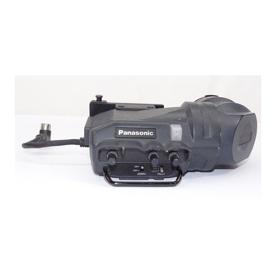
1.5-inch Electronic View Finder / 2-inch Electronic View Finder
AJ-VF15BP/E / AJ-VF20WBP/E
Please use this manual together with the service manual for
Model
No. AJ-VF15BP/E, AJ-VF20WBP/ E, Order No.
VSD9908M905.
2004 Matsushita Electric Industrial Co., Ltd. All rights reserved.
1
Advertisement
Table of Contents

Subscribe to Our Youtube Channel
Related Manuals for Panasonic AJ-VF15BP


Summary of Contents for Panasonic AJ-VF15BP
- Page 1 ORDER NO. BSD04090210 1.5-inch Electronic View Finder / 2-inch Electronic View Finder AJ-VF15BP/E / AJ-VF20WBP/E Please use this manual together with the service manual for Model No. AJ-VF15BP/E, AJ-VF20WBP/ E, Order No. VSD9908M905. 2004 Matsushita Electric Industrial Co., Ltd. All rights reserved.
- Page 2 Unauthorized copying and distribution is a violation of law. Please refer to the Operating Instructions in the appendix folder. / (Go to Appendix List) 1. Service Manual for AJ-VF15BP/E,AJ-VF20WBP/E...
-
Page 3: Sec 1 Operating Instructions
ORDER NO. VSD9908M905D20 1.5"Electronic View Finder AJ-VF15P/E 2"Electronic View Finder Sec.1 Operating Instructions AJ-VF20WP/E Sec.2 Disassembly procedures Sec.3 Electrical adjustment procedures Sec.4 Block Diagrams,Schematic Diagrams& Circuit Board Diagrams Sec.5 Exploded Views & Replacement Parts List c 1999 Matsushita Electric Industrial Co., Ltd. All rights reserved. Unauthorized copying and distribution is a violation of law. -
Page 4: Table Of Contents
CONTENTS SAFETY PRECAUTIONS SEC 1 Operating Instructions Precautions for use........................1-1 Parts and their functions ......................1-2 Adjusting the Viewfinder......................1-2 Mounting the Microphone......................1-3 SEC 2 Disassembly Procedures 1. Mounting unit removal......................2-1 2. Microphone holder removal..................... 2-1 3. Eye piece unit removal......................2-1 4. -
Page 5: Precautions For Use
SECTION OPERATING INSTRUCTIONS CONTENTS Precautions for Use Parts and their Functions Adjusting the Viewfinder Mounting the Microphone... -
Page 6: Parts And Their Functions
Features Parts and Their Functions OThe high-resolution CRT delivers superb picture sharpness, making focusing easier. OThe low-flare CRT makes the screen clear and easy on the eyes. OThe large eyecup aperture makes it possible to see the screen even when holding the viewfinder at some distance from your eye. - Page 7 Parts and Their Functions Parts and Their Functions BRIGHT (Brightness) Knob Internal LEDs The lamp and picture tube indications will differ depending on the camera used with the Adjusts the brightness of the screen inside the viewfinder. The setting of this control has no effect on the output signal of the camera.
-
Page 8: Adjusting The Viewfinder
Adjusting the Viewfinder Adjusting the Viewfinder Adjusting the Mounting Height of the Viewfinder Mounting the Viewfinder The mounting height of the viewfinder will differ depending on the camera on which it is Confirm that the POWER switch of the camera is “OFF”. mounted. - Page 9 Adjusting the Viewfinder Adjusting the Viewfinder Position Adjustment Diopter Adjustment Lift up the viewfinder forward-backward/left-right position clamp lever to disengage Set the POWER switch of the camera to “ON”. A picture will appear in the the lock. viewfinder. Lever Turn the diopter adjustment ring to adjust the diopter so that the viewfinder picture can be clearly seen.
-
Page 10: Mounting The Microphone
Adjusting the Viewfinder Mounting the Microphone Detaching the Eyecup Follow the steps below to install the AJ-MC700P microphone kit (sold separately). If dust has adhered to the CRT screen or mirror, detach the eyecup and remove it. Open the microphone holder. <Note>... -
Page 11: Mounting Unit Removal
SECTION DISASSEMBLY PROCEDURES CONTENTS 1.Mounting Unit Removal 2.Microphone Holder Removal 3.Eye Piece Rubber Removal 4.Eye Piece Unit Removal 5.Upper Case Removal 6.Bottom Case Removal 7.CRT Unit Removal 8.Sub 1 P.C.Board Removal 9.Sub 2 P.C.Board Removal 10.MAIN P.C.Board Removal 11.Guard Bar Removal 12.LED P.C.Board Removal 13.Back Tally Base Removal... - Page 12 Disassemble procedures 3. Eye Piece Rubber Removal 1. Mounting Unit Removal Unscrew 2 screws (A) so that the mounting plate can be removed. Screw(A) Carefully tear off the portions of the Eye piece. Note: When assembling the eye piece unit, align the markers as shown in the figure above.
-
Page 13: Upper Case Removal
7. CRT Unit Removal 5. Upper Case Removal 1. Unscrew 2 screws (E) and 1 screw (F). 1. Unscrew 3 screws (D) so that the upper case can 2. Slowly and carefully pullout the CRT unit. be removed. screw (D) screw (D) Caution : 1) Do not wipe the surface of the mirror because the special corting has... -
Page 14: Sub 1 P.c.board Removal
8. Sub 1 P.C.Board Removal 10. MAIN P.C.Board Removal Casually disconnect connector CN21 and unscrew 1. Carefully disconnect connectors (CN1) so that 2 screws (G) so that the Sub 1 P.C.Board can be the EVF Cable can be removed. removed. 2. -
Page 15: Led P.c.board Removal
12. LED P.C.Board Removal 13. Back Tally Base Removal 1. Carefully disconnect connectors (A) and unscrew Unscrew 2 screws (L) so that the Back Tally Base 4 screws (J) so that the CRT unit can be removed. can be removed. screw (L) screw (T) screw (T) - Page 16 SECTION ELECTRICALADJUSTMENT PROCEDURES SEC 3 electrical adjustment procedures 1-1. measuring equipment and special tools................. 3-1 1-2. Adjustment preparation ......................3-1 2. Electrical Adjustment (AJ-VF15) 2-1. Power voltage adjustment..................... 3-2 2-2. V Hold adjustment........................ 3-2 2-3. H Hold adjustment ....................... 3-2 2-4.
-
Page 17: Measuring Equipment And Special Tools
1. Preparation 1-1 Measuring Equipment and Special Tools. Item Recommend Stuff Note Digital Volt Meter Frequency Counter Registration Chart VFK0673 Use For High Voltage meas- High voltage prove urement Screwdriver(for adjust- The screwdriver use the made ment).Hex Wrench by resin The camera recorder becomes necessary separately for the all-kind control such as the aspect changing to the others. -
Page 18: Electrical Adjustment (Aj-Vf15)
PEAKING VR to the minimum position. 2. Electrical Adjustment Procedure 2. Connect the high voltage voltmeter with the high voltage (AJ-VF15) prove to the connector between the FBT and anode cap. 3. Adjust RV5 so that the High Voltage is within specification. -
Page 19: Brightness Adjustment
Black out confirmation Fig.3 Brightness Adjustment 2-7. High voltage regulator Adjustment BOARD MAIN BOARD SPEC 6.0V+/-0.1V A1 (1.5Scale) TEST TP11 (IC9 7pin) ADJUST RV6 [OPAMP-ADJ] V-BLK Portion M.EQ Digital Volt meter CRT Frame Portion A1 = A2 1. Set the BRIGHT VR.CONTRAST VR and PEAKING VR to the minimum position. -
Page 20: Peaking Balance Adjustment
2-9. Peaking Balance Adjustment 3-2. V. Hold Adjustment BOARD MAIN BOARD / SUB2 BOARD BOARD MAIN BOARD / SUB1 BOARD SPEC 3.9v+/-0.1v SPEC 48+/-0.5Hz (NTSC) Peaking A = Peaking B 38+/-0.5Hz (PAL) TEST Pin 16 of CN1 and EVF Picture TEST TP12 (Pin 4 of CN2)/ MAIN BOARD ADJUST... -
Page 21: Screen Size Adjustment1 (4:3Mode)
Fig.5 Registration Chart 3-5. Screen Size Adjustment1 (4:3Mode) BOARD MAIN BOARD / SUB1 BOARD TEST EVF Screen ADJUST RV4 [H-SIZE(HLC)] / MAIN BOARD RV3 [V-SIZE] / SUB1 BOARD A1(1.5 Scale) 1. Open the on-screen menu on the camera recorder in the 16:9 mode so that the EVF screen is 16:9. -
Page 22: High Voltage Regulator Adjustment
(16:9 Mode) BOARD MAIN BOARD BOARD SUB2 BOARD SPEC 635mV+/-15mV (DC) SPEC Pedestal Portion is Just Dark TEST TP5 (Hot) & TP6 GND (Pins 3 & 4 CN5) TEST EVF Screen ADJUST RV7 [VH-ADJ] ADJUST RV6 [SUB BRIGHT (WIDE)] M.EQ Digital Voltmeter SIGNAL Color Bar Signal from Camera... - Page 23 SECTION 4 BLOCK DIAGRAMS SCHEMATIC DIAGRAMS CIRCUIT BOARD DIAGRAMS Note: Do not use the part number shown on the schematic diagram or P.C.Board layout for ordering. The correct part number for ordering is shown in the Exploded Views / Parts List section.
-
Page 24: Evf Block Diagrams
CONTENTS EVF BLOCK DIAGRAMS BLK1 SCM1 MAIN SCHEMATICK DIAGRAMS SCM2 MAIN SUB1 SCHEMATICK DIAGRAMS SCM3 MAIN SUB2 SCHEMATICK DIAGRAMS MAIN P.C.BOARD PTN1 MAIN SUB1 P.C.BOARD PTN1 MAIN SUB2 P.C.BOARD PTN2 LED P.C.BOARD PTN2 CAUTION MARK INDICATES THE PRIMARY CIRCUIT TO DISTINGUISH THE PRIMARY FROM THE SECONDARY CIRCUIT. PAY ATTENTION NOT TO RECEIVE AN ELECTRIC SHOCK DURING REPAIR AND SERVICE OF THE PRODUCTS. - Page 25 EVF BLOCK DIAGRAM MAIN P.C. BOARD SUB1(H.V DEF) P.C.BOARD EVF CONNECT +9.5V UNREG IN UNREG IN +9.5V MAIN P.C BOARD UNREG IN UNREG IN VF VIDEO H-HOLD IC8.IC9.Q4 SP CLK PHASE 13 14 SP WR HORIZONTAL HORIZONTAL 9.5V ADJ HD OUT +B REG CLAMP DRIVE...
- Page 26 CN41 C4081 IC2D IC2A TC74HC164HF TC74HCO8AF REC/TALLY EFFECT REC/TALLY BATT EFFECT BATT IC3A IC2C VTR SAVE TC7WO4F G TALLY SPEAR 1 VTR SAVE SPEAR 2 SPEAR 3 IC2B TA-CB TA-CB IC3B R104 4.7K 4.7K M66311FP R103 5 OE 16:9/4:3 3.3K R TALLY REC/TALLY G TALLY...
- Page 27 CN21 CN22 TP13 V.DY +V.DEF +V.DEF 3.3K VIDEO IN TP14 CL-200HRC (BACK TALLY) C4081 -V.DEF -V.DEF REC/TALLY 16:9 IN 4.7K 8.2K IMZ1 V.BLK OUT 2.2K C.SYNC OUT HD DUT VF15 ONLY TA-CB 1SS302 TA-CB TA-CA X RAY TRIG 0.1U 220p 6.8K AFC GATE V.BLKG...
- Page 28 8.2K CN31 100K C4102 C4081 0.01U +9.5V IN 1.8K 2.7K C4178 C4178 C4102 100p VIDEO IN 4.7U DL 1 HZK4ALL TP15 TA-CA 6.8K CL-200HR VF20W ONLY TG355ENK-6338 C4178 1SS302 DL 1 C4102 500K CL-200HR 120ns 1SS302 2.2K C4178 1.6K 4.7K C4178 C4081 TALLY IN...
- Page 29 SECTION EXPLODED VIEWS & REPLACEMENT PARTS LIST Note: 1. *Be sure to make your orders of replacement parts according to this list. 2. Unless otherwise specified, all resistors are in OHMS, K=1,000 OHMS, all capacitors are in MICROFARADS ( F), P= 3.
- Page 30 CONTENTS Packing Parts Assembly PRT1 PRT2 Mechanical Parts Assembly PRT4 Electrical Replacement Parts List...
-
Page 31: Packing Parts Assembly
PACKING PARTS ASSEMBLY PACKING PARTS ASSEMBLY AJ-YAD230P Ref.No. Part No. Part Name & Description Pcs Remarks Ref.No. Part No. Part Name & Description Pcs Remarks VQT8082 OPERATING INSTRUCTION VPG0A71 PACKING CASE VPN5247 CUSHION A VPN5248 CUSHION B VPN5249 CUSHION C VPN5250 CUSHION D VPN5251... - Page 32 AJ-VF15P_E/VF20WP_E Ref.No. Part No. Part Name & Description Pcs Remarks Ref.No. Part No. Part Name & Description Pcs Remarks VYK9294 TOP CASE ASS'Y VYK9295 BOTTOM CASE ASS'Y VXF0172 MIC HOLDER ASS'Y VMC1513 PLATE SPRING VKH0389 GUARD BAR VMG1217 CASE PACKING (1) VMG1218 CASE PACKING (2) VGU8170...
-
Page 33: Mechanical Parts Assembly
MECHANICAL PARTS ASSEMBLY 53 54 PRT-3... - Page 34 AJ-VF15P/E Ref.No. Part No. Part Name & Description Pcs Remarks Ref.No. Part No. Part Name & Description Pcs Remarks TL1453CNS •¡ E1 VEP20780B MAIN P.C.BOARD 1 (RTL)AJ-VF15P TC4S01F •¡ E1 VEP20780D MAIN P.C.BOARD 1 (RTL)AJ-VF15E TC4W53F UPC358G2-E2IC •¡ E2 VEP20781B SUB 1 P.C.BOARD 1 (RTL)AJ-VF15P IC10...
- Page 35 AJ-VF15P/E Ref.No. Part No. Part Name & Description Pcs Remarks Ref.No. Part No. Part Name & Description Pcs Remarks R110 VRE0218 M.RESISTOR ERJ6GEYF473M.RESISTOR CH 1/10W 47K 1 R111 ERJ6GEYG101 M.RESISTOR CH 1/10W 100 1 ERJ6GEYJ224M.RESISTOR CH 1/10W 220K 1 ERJ6GEYG562 M.RESISTOR CH 1/10W 5.6K 1 VRV0303B102 V.RESISTOR ERJ6GEYG103 M.RESISTOR CH 1/10W 10K 1 VRV0303B502 V.RESISTOR...
- Page 36 AJ-VF15P/E Ref.No. Part No. Part Name & Description Pcs Remarks Ref.No. Part No. Part Name & Description Pcs Remarks ERJ6GEYG101 M.RESISTOR CH 1/10W 100 1 ERJ6GEYG332 M.RESISTOR CH 1/10W 3.3K 1 R8-10 ERJ6GEYJ551M.RESISTOR CH 1/10W 550 3 R11,12 ERJ6GEYG182 M.RESISTOR CH 1/10W 1.8K 2 ERJ6GEYF393M.RESISTOR CH 1/10W 39K 1 ERJ6GEYG223 M.RESISTOR CH 1/10W 22K 1 ERJ6GEYJ551M.RESISTOR CH 1/10W 550 1...
- Page 37 AJ-VF15P/VF20WP Ref.No. Part No. Part Name & Description Pcs Remarks Ref.No. Part No. Part Name & Description Pcs Remarks VMC1513 PLATE SPRING VKH0389 GUARD BAR VMG1217 CASE PACKING (1) VMG1218 CASE PACKING (2) VGU8170 TALLY KNOB VGQ5321 TALLY BASE VGL0837 TALLY COVER VMG1219 TALLY SHEET...
- Page 38 AJ-VF20WP/E Ref.No. Part No. Part Name & Description Pcs Remarks Ref.No. Part No. Part Name & Description Pcs Remarks M66311FP •¡ E1 VEP20780B MAIN P.C.BOARD 1 (RTL)AJ-VF20WP TL1453CNS VEP20780C MAIN P.C.BOARD 1 (RTL)AJ-VF20WE TC4S01F IC7,C8 TC4W53F •¡ E2 VEP20781A SUB 1 P.C.BOARD 1 (RTL)AJ-VF20WP UPC358G2-E2IC VEP20781C...
- Page 39 AJ-VF20WP/E Ref.No. Part No. Part Name & Description Pcs Remarks Ref.No. Part No. Part Name & Description Pcs Remarks ERJ6GEYJ5R6M.RESISTOR CH 1/10W 5.6 1 ERJ6GEYG222 M.RESISTOR CH 1/10W 2.2K 1 R101 ERJ6GEY0R00 M.RESISTOR CH 1/10W ERJ6GEYF473M.RESISTOR CH 1/10W 47K 1 R104,05 ERJ6GEYG103 M.RESISTOR CH 1/10W 10K 2 ERJ6GEYJ224M.RESISTOR CH 1/10W 220K 1...
- Page 40 AJ-VF20WP/E Ref.No. Part No. Part Name & Description Pcs Remarks Ref.No. Part No. Part Name & Description Pcs Remarks ERJ6GEYG332 M.RESISTOR CH 1/10W 3.3K 1 R8-10 ERJ6GEYJ551M.RESISTOR CH 1/10W 550 3 R11,12 ERJ6GEYG182 M.RESISTOR CH 1/10W 1.8K 2 ERJ6GEYF393M.RESISTOR CH 1/10W 39K 1 ERJ6GEYG223 M.RESISTOR CH 1/10W 22K 1 ERJ6GEYJ551M.RESISTOR CH 1/10W 550 1 R16,17...
- Page 41 AJ-VF20WP Ref.No. Part No. Part Name & Description Pcs Remarks Ref.No. Part No. Part Name & Description Pcs Remarks VMC1513 PLATE SPRING VKH0389 GUARD BAR VMG1217 CASE PACKING (1) VMG1218 CASE PACKING (2) VGU8170 TALLY KNOB VGQ5321 TALLY BASE VGL0837 TALLY COVER VMG1219 TALLY SHEET...
- Page 42 Replacement Parts List 2-inch Electronic View Finder AJ-VF20WBP/E Please file and use this manual together with the service manual for Model No.AJ-VF15BP/E, AJ- VF20WBP/E, Order No. VSD9908M905. © 2004 Matsushita Electric Industrial Co., Ltd. All rights reserved. Unauthorized copying and distribution is a violation of law.
- Page 43 DC 12 V (supplied by camera) Power consumption: 2.1 W (AJ-VF15BP, AJ-VF15BE) 2.7 W (AJ-VF20WBP, AJ-VF20WBE) Picture tube: 1.5-inch high-resolution monochrome picture tube (AJ-VF15BP, AJ-VF15BE) 2-inch high-resolution monochrome picture tube (AJ-VF20WBP, AJ-VF20WBE) Horizontal resolution: 600 lines (center, typical, 4 : 3 mode)
- Page 44 MECHANICAL PARTS ASSEMBLY 54 55 PRT-1...
- Page 45 MECHANICAL PARTS ASSEMBLY R e f . N o . P a r t N o . P a r t N a m e & D e s c r i p t i o n P c s R e m a r k s R e f .
- Page 46 PACKING PARTS ASSEMBLY PACKING PARTS ASSEMBLY Ref.No. Part No. Part Name & Description Remarks Ref.No. Part No. Part Name & Description Remarks VQT0L51 OPERATING INSTRUCTION VQL9822 PACKING LABEL FOR_AJVF15BP/E VPG0A71 PACKING CASE VQL0A24 PACKING LABEL FOR_AJVF20WBP/E VPN5247 CUSHION A KH82-05 PROTECT BAG VPN5248 CUSHION B...
-
Page 47: Electrical Replacement Parts List
Components identified with the mark have special characteristics for safety. When replacing any of these component, use only the same type. ELECTRICAL REPLACEMENT PARTS LIST AJ-VF15BP Ref.No. Part No. Part Name & Description Remarks Ref.No. Part No. Part Name & Description... - Page 48 Components identified with the mark have special characteristics for safety. When replacing any of these component, use only the same type. Ref.No. Part No. Part Name & Description Remarks Ref.No. Part No. Part Name & Description Remarks R101 ERJ6GEY0R00 M.RESISTOR CH 1/10W ERJ6GEYF123 M.RESISTOR CH 1/10W...
- Page 49 Components identified with the mark have special characteristics for safety. When replacing any of these component, use only the same type. Ref.No. Part No. Part Name & Description Remarks Ref.No. Part No. Part Name & Description Remarks ERJ6GEYG223 M.RESISTOR CH 1/10W ERJ6GEYG101 M.RESISTOR CH 1/10W ERJ6GEYG332...
- Page 50 Components identified with the mark have special characteristics for safety. When replacing any of these component, use only the same type. ELECTRICAL REPLACEMENT PARTS LIST AJ-VF15BE Ref.No. Part No. Part Name & Description Remarks Ref.No. Part No. Part Name & Description Remarks TC74HC08AF 1 C0JBAA000084...
- Page 51 Components identified with the mark have special characteristics for safety. When replacing any of these component, use only the same type. Ref.No. Part No. Part Name & Description Remarks Ref.No. Part No. Part Name & Description Remarks R101 ERJ6GEY0R00 M.RESISTOR CH 1/10W ERJ6GEYF123 M.RESISTOR CH 1/10W...
- Page 52 Components identified with the mark have special characteristics for safety. When replacing any of these component, use only the same type. Ref.No. Part No. Part Name & Description Remarks Ref.No. Part No. Part Name & Description Remarks ERJ6GEYG103 M.RESISTOR CH 1/10W ERJ6GEYG102 M.RESISTOR CH 1/10W ERJ6GEYG273...
- Page 53 Components identified with the mark have special characteristics for safety. When replacing any of these component, use only the same type. ELECTRICAL REPLACEMENT PARTS LIST AJ-VF20WBP Ref.No. Part No. Part Name & Description Remarks Ref.No. Part No. Part Name & Description Remarks TC74HC164AF ...
- Page 54 Components identified with the mark have special characteristics for safety. When replacing any of these component, use only the same type. Ref.No. Part No. Part Name & Description Remarks Ref.No. Part No. Part Name & Description Remarks ERJ6GEYG680 M.RESISTOR CH 1/10W ERJ6GEYG683 M.RESISTOR CH 1/10W ERJ6GEYG101...
- Page 55 Components identified with the mark have special characteristics for safety. When replacing any of these component, use only the same type. Ref.No. Part No. Part Name & Description Remarks Ref.No. Part No. Part Name & Description Remarks ERJ6GEYG103 M.RESISTOR CH 1/10W ERJ6GEYG102 M.RESISTOR CH 1/10W ERJ6GEYG273...
- Page 56 Components identified with the mark have special characteristics for safety. When replacing any of these component, use only the same type. ELECTRICAL REPLACEMENT PARTS LIST AJ-VF20WBE Ref.No. Part No. Part Name & Description Remarks Ref.No. Part No. Part Name & Description Remarks TC74HC164AF ...
- Page 57 Components identified with the mark have special characteristics for safety. When replacing any of these component, use only the same type. Ref.No. Part No. Part Name & Description Remarks Ref.No. Part No. Part Name & Description Remarks ERJ6GEYG680 M.RESISTOR CH 1/10W ERJ6GEYG683 M.RESISTOR CH 1/10W ERJ6GEYG101...
- Page 58 Components identified with the mark have special characteristics for safety. When replacing any of these component, use only the same type. Ref.No. Part No. Part Name & Description Remarks Ref.No. Part No. Part Name & Description Remarks ERJ6GEYG103 M.RESISTOR CH 1/10W ERJ6GEYG102 M.RESISTOR CH 1/10W ERJ6GEYG273...
- Page 59 ZCD0409BYNE265E266B...
Need help?
Do you have a question about the AJ-VF15BP and is the answer not in the manual?
Questions and answers