Table of Contents
Advertisement
Available languages
Available languages
Quick Links
Operating Instructions/Bedienungsanleitung
Mode d'emploi/Istruzioni per l'uso
Instrucciones de funcionamiento
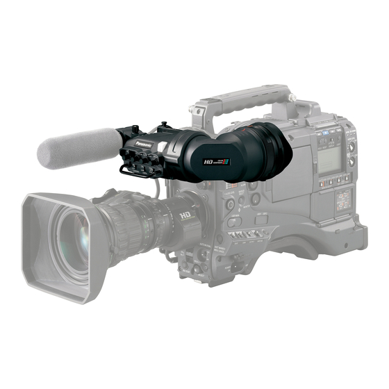
1-inch Electronic HD Color View Finder
1-Zoll Elektronischer HD-Farbe-Sucher
HD Couleur Viseur électronique de 1 pouce
HD Colore Mirino Elettronico da 1 pollici
HD Color Visor Electrónico de 1 pulgadas
1
HD
Before operating this product, please read the instructions carefully and save this
manual for future use.
Bitte lesen Sie diese Bedienungsanleitung vor der Inbetriebnahme dieses Produkts
aufmerksam durch, und bewahren Sie sie für späteres Nachschlagen auf.
Avant d'utiliser l'appareil, lire attentivement ce mode d'emploi, et le conserver à des
fins de référence ultérieure.
Prima di far funzionare questo prodotto, leggere attentamente le istruzioni e
conservare questo manuale per riferimenti futuri.
Antes de utilizar este producto, lea cuidadosamente las instrucciones y guarde este
manual por si tiene que utilizarlo en el futuro.
"
"
2
4
F0509T0 -F @
VQT2C51
Printed in Japan
Advertisement
Chapters
Table of Contents

Related Manuals for Panasonic AJ-CVF100G


Summary of Contents for Panasonic AJ-CVF100G
- Page 1 Operating Instructions/Bedienungsanleitung Mode d’emploi/Istruzioni per l’uso Instrucciones de funcionamiento 1-inch Electronic HD Color View Finder 1-Zoll Elektronischer HD-Farbe-Sucher HD Couleur Viseur électronique de 1 pouce HD Colore Mirino Elettronico da 1 pollici HD Color Visor Electrónico de 1 pulgadas Before operating this product, please read the instructions carefully and save this manual for future use.
-
Page 2: Read This First
ENGLISH Read this first! For General _ DO NOT REMOVE PANEL COVERS BY UNSCREWING THEM. No user serviceable parts inside. Refer servicing to qualified service personnel. WARNING: TO REDUCE THE RISK OF FIRE OR SHOCK HAZARD, DO NOT EXPOSE THIS EQUIPMENT TO RAIN OR MOISTURE. - Page 3 Read this first! (Continued) For USA This device complies with part 15 of the FCC Rules. Operation is subject to the following two conditions: (1) This device may not cause harmful interference, and (2) this device must accept any interference received, including interference that may cause undesired operation. FCC Note: This equipment has been tested and found to comply with the limits for a class B digital device, pursuant to Part 15 of the FCC Rules.
-
Page 4: Table Of Contents
Table of Contents Read this first! ....................1 Features ......................4 Parts and Their Functions ................4 Adjusting the Viewfinder .................. 7 Attaching the Viewfinder....................7 Adjusting the Viewfinder’s left-right position..............8 Adjusting the Viewfinder’s front-back position............... 8 Detaching the Viewfinder ....................9 Diopter Adjustment...................... -
Page 5: Features
Features It is compatible with Multi-format (1080i/720P). High resolution color LCD panel will display fine images, making it easy to focus. With the 1-inch LCOS panel, it has realized fast response and high resolution equivalent to a CRT. This unit is same size as the conventional B&W HD viewfinder, making it possible to replace without any modification. - Page 6 Parts and Their Functions (Continued) TALLY Switch Controls the front tally lamp. HIGH: Makes the front tally lamp brighter. OFF: Turns the tally lamp off. LOW: Makes the front tally lamp dimmer. PEAKING Control Adjusts the outlines of the images in the viewfinder to make focusing easier. The setting of this control has no effect on the output signal of the camera.
- Page 7 Parts and Their Functions (Continued) Internal LEDs Indicators and displayed screen content are different depending on the camera used. Refer to the instruction manual of the camera for details. TALLY / REC BATT SAVE Green TALLY Indicator Lights in green when a green TALLY signal is received from the camera control unit. TALLY/REC Indicator Lights in red during the recording, or when the red TALLY signal is received from the camera control unit.
-
Page 8: Adjusting The Viewfinder
Adjusting the Viewfinder Attaching the Viewfinder Confirm that the POWER switch of the camera is “OFF”. Insert the plug into the connection jack of the viewfinder. <Note> Be sure to insert the plug all the way into the connection jack. Loosen the ring. -
Page 9: Adjusting The Viewfinder's Left-Right Position
Adjusting the Viewfinder (Continued) Adjusting the Viewfinder’s left-right position Loosen the viewfinder left-right position anchoring ring. Slide the viewfinder to the left or right, and adjust it to a position that allows easy viewing. Viewfinder left-right Tighten the ring. position anchoring ring Tighten the viewfinder left-right position anchoring ring. -
Page 10: Detaching The Viewfinder
Adjusting the Viewfinder (Continued) Detaching the Viewfinder Confirm that the POWER switch of the camera is “OFF”. Loosen the viewfinder left-right position anchoring ring. While pulling up the viewfinder stopper, remove the viewfinder by sliding it in the direction of the arrow. Loosen the ring. -
Page 11: Diopter Adjustment
Adjusting the Viewfinder (Continued) Diopter Adjustment Set the POWER switch of the camera to “ON”. A picture will appear in the viewfinder. Turn the diopter adjustment ring to adjust the diopter so that the viewfinder picture can be clearly seen. Diopter adjustment ring Screen Adjustment Adjust the condition of the viewfinder screen. -
Page 12: Cleaning The Eyepiece
Cleaning the Eyepiece Remove the eyepiece to clean off any dust that got on the LCOS panel screen or mirror. <Note> Do not wipe the mirror surface under any circumstances as it has been specially treated. Dust which has adhered to the mirror should be blown away with a blower, etc. Turn the lock ring as far as Alignment marks Eyepiece... -
Page 13: Attaching The Microphone
Attaching the Microphone Follow the steps below to install the AJ-MC700P or the AJ-MC900G microphone kit (sold separately). Open the microphone holder. Viewfinder Microphone holder Attach the microphone. Plug the microphone connector cable into the MIC IN jack. MIC IN jack E-12... -
Page 14: Specifications
Specifications Power supply: DC 12 V (supplied by camera) Power consumption: 5.0 W indicates safety information. Display panel: 1-inch LCOS panel Image system: Compatible with automatic switching to the following images 1080/50i, 1080/59.94i, 1080/60i, 720/59.94P, 720/60P External adjustment controls: Controls (BRIGHT, CONTRAST, CHROMA, PEAKING) Switches (TALLY HIGH/OFF/LOW, ZEBRA ON/OFF, CHROMA ON/OFF) - Page 15 Information on Disposal for Users of Waste Electrical & Electronic Equipment (private households) This symbol on the products and/or accompanying documents means that used electrical and electronic products should not be mixed with general household waste. For proper treatment, recovery and recycling, please take these products to designated collection points, where they will be accepted on a free of charge basis.
- Page 16 DEUTCH Bitte lesen! _ Öffnen Sie nicht das Gerät durch Abschrauben von Gehäuseteilen. Im Geräteinneren befinden sich keine Teile, die vom Benutzer gewartet werden können. Wartungs- und Reparaturarbeiten grundsätzlich autorisiertem Kundendienstpersonal überlassen. WARNUNG: ZUR REDUZIERUNG DER GEFAHR VON BRAND UND ELEKTRISCHEM SCHLAG DIESES GERÄT WEDER NÄSSE NOCH FEUCHTIGKEIT AUSSETZEN.
-
Page 17: Merkmale
Merkmale Es ist mit dem Multi-Format kompatibel (1080i/720P). Ein hoch auflösendes Farb-LCD-Panel zeigt genaue Bilder an, was das Fokussieren einfach macht. Mit dem 1-Zoll LCOS-Panel wurden eine schnelle Ansprache und eine hohe Auflösung erreicht, vergleichbar mit einem CRT. Dieses Gerät hat die gleiche Größe wie ein konventioneller Schwarzweiß-HD-Sucher, was einen Austausch ohne eine Veränderung ermöglicht. - Page 18 Teile und ihre Funktionen (Fortsetzung) Signallampenschalter [TALLY] Steuert die vordere Signallampe. HIGH: Erhöht die Helligkeit der vorderen Signallampe. OFF: Schaltet die Signallampe aus. LOW: Verringert die Helligkeit der vorderen Signallampe. Regler PEAKING Dient zur Einstellung der Bildkonturen im Sucher, um die Scharfeinstellung zu erleichtern. Die Einstellung dieses Reglers hat keinen Einfluß...
- Page 19 Teile und ihre Funktionen (Fortsetzung) Interne LEDs Inhalte der Anzeigen und Bildschirmanzeigen unterscheiden sich davon, welche Kamera benutzt wird. Einzelheiten sind der Bedienungsanleitung der Kamera zu entnehmen. TALLY / REC BATT SAVE Grüne TALLY-Anzeige Leuchtet grün auf, wenn ein grünes TALLY-Signal von der Bedienungseinheit der Kamera empfangen wird.
-
Page 20: Einstellen Des Suchers
Einstellen des Suchers Anbringen des Suchers Sicherstellen, daß sich der Schalter POWER der Kamera in der AUS-Stellung befindet. Den Stecker in die Anschlußbuchse des Suchers einführen. <Hinweis> Führen Sie den Stecker bis zum Anschlag in die Anschlußbuchse ein. Den Ring lösen. Querpositions-Feststellring des Suchers Lösen Sie den Querpositions-Feststellring des Suchers. -
Page 21: Einstellen Der Querposition Des Suchers
Einstellen des Suchers (Fortsetzung) Einstellen der Querposition des Suchers Lösen Sie den Querpositions-Feststellring des Suchers. Schieben Sie den Sucher nach links oder rechts, um seine Position so einzustellen, dass der Suchermonitor bequem ablesbar ist. Den Ring anziehen. Querpositions-Feststellring des Suchers Ziehen Sie den Querpositions-Feststellring des Suchers an. -
Page 22: Abnehmen Des Suchers
Einstellen des Suchers (Fortsetzung) Abnehmen des Suchers Sicherstellen, daß sich der Schalter POWER der Kamera in der AUS-Stellung befindet. Lösen Sie den Querpositions-Feststellring des Suchers. Entfernen Sie den Sucher durch Schieben in Pfeilrichtung, während Sie den Sucheranschlag hochziehen. Den Ring lösen. Sucheranschlag Lösen Sie das Sucherkabel und das Mikrofonkabel aus den Kabelklemmen, und trennen Sie die Kabel ab. -
Page 23: Dioptrieneinstellung
Einstellen des Suchers (Fortsetzung) Dioptrieneinstellung Den Schalter POWER der Kamera auf die EIN-Stellung stellen. Ein Bild erscheint im Sucher. Das Okular durch Drehen des Dioptrien-Einstellrings so einstellen, daß das Sucherbild scharf ist. Dioptrien-Einstellring Sucherschirmeinstellung Den Zustand des Sucherschirms einstellen. Helligkeit: Den Regler BRIGHT drehen. Kontrast: Den Regler CONTRAST drehen. -
Page 24: Reinigen Des Sucherokulars
Reinigen des Sucherokulars Entfernen Sie das okular, um Staub zu entfernen, der auf den LCOS-Panel des Bildschirms oder des Spiegels gelangt ist. <Hinweis> Die Spiegeloberfläche darf unter keinen Umständen abgewischt werden, da sie speziell vergütet ist. Am Spiegel haftender Staub sollte mit einem Blasepinsel oder dergleichen entfernt werden. -
Page 25: Anbringen Des Mikrofons
Anbringen des Mikrofons Führen Sie die folgenden Schritte aus, um den Mikrofonsatz AJ-MC700P oder AJ- MC900G (getrennt erhältlich) zu montieren. Den Mikrofonhalter öffnen. Sucher Mikrofonhalter Das Mikrofon anbringen. Den Stecker des Mikrofonkabels an die Buchse MIC IN anschließen. Buchse MIC IN G-10... -
Page 26: Technische Daten
Technische Daten Stromversorgung: 12 V Gleichspannung (Versorgung durch Kamera) Leistungsaufnahme: 5,0 W ist die Sicherheitsinformation. Anzeige: 1-Zoll LCOS-Panel Bildsystem: Kompatibel mit automatischer Umschaltung auf folgende Bilder 1080/50i, 1080/59,94i, 1080/60i, 720/59,94P, 720/60P Externe Regler und Schalter: Regler (BRIGHT, CONTRAST, CHROMA, PEAKING) Schalter (TALLY HIGH/OFF/LOW, ZEBRA ON/OFF, CHROMA ON/OFF) Zulässiger Temperaturbereich:... - Page 27 Benutzerinformationen zur Entsorgung von elektrischen und elektronischen Geräten (private Haushalte) Dieses Symbol auf Produkten und/oder begleitenden Dokumenten bedeutet, dass verbrauchte elektrische und elektronische Produkte nicht mit gewöhnlichem Haushaltsabfall vermischt werden sollen. Bringen Sie zur ordnungsgemäßen Behandlung, Rückgewinnung und Recycling diese Produkte zu den entsprechenden Sammelstellen, wo sie ohne Gebühren entgegengenommen werden.
- Page 28 FRANÇAIS Lire ces informations en premier ! _ Ne pas dévisser le couvercle. Il ne se trouve à l’intérieur aucune pièce qui puisse être réparée par l’utilisateur. Confier toute réparation à un personnel qualifié. AVERTISSEMENT: POUR RÉDUIRE LES RISQUES D’INCENDIE OU DE CHOC ÉLECTRIQUE, ÉVITEZ D’EXPOSER CET APPAREIL À...
- Page 29 Table des matières Lire ces informations en premier ! ..............1 Caractéristiques ....................2 Les commandes et leurs fonctions ..............3 Réglage du viseur ..................... 5 Montage du viseur ......................5 Réglage de la position gauche-droite du viseur ............6 Réglage de la position avant-arrière du viseur ..............6 Retrait du viseur ......................7 Réglage de la correction dioptrique................8 Réglage de l’écran......................8...
-
Page 30: Les Commandes Et Leurs Fonctions
Les commandes et leurs fonctions PEAKING CHROMA CONTRAST BRIGHT Commande PEAKING Commutateur de saturation Il permet de régler les contours de (CHROMA) l’image dans le viseur de façon à les Bascule l’affichage des images entre rendre plus nets. Le réglage de cette Couleurs et B&W sur le viseur. - Page 31 Les commandes et leurs fonctions (suite) Voyant de signalisation avant S’allume pendant la prise de vues TALLY / REC lorsque le commutateur TALLY est réglé sur HIGH ou LOW. ailleurs, clignote à titre d’avertissement, de la même manière que le voyant REC dans le viseur. La luminosité...
-
Page 32: Réglage Du Viseur
Réglage du viseur Montage du viseur Vérifier que l’interrupteur POWER de la caméra est éteint (“OFF”). Insérer la fiche dans la prise de raccordement du viseur. <Remarque> Bien insérer la fiche à fond dans la prise de raccordement. Desserrer la bague. Bague d’ancrage de la position gauche-droite du viseur Desserrer la bague d’ancrage de la position gauche-droite du viseur. -
Page 33: Réglage De La Position Gauche-Droite Du Viseur
Réglage du viseur (suite) Réglage de la position gauche-droite du viseur Desserrer la bague d’ancrage de la position gauche-droite du viseur. Glisser le viseur vers la gauche ou vers la droite, et le régler sur la position permettant une vue facile des données sur l’écran. Bague d’ancrage de la position Serrer la bague. -
Page 34: Retrait Du Viseur
Réglage du viseur (suite) Retrait du viseur Vérifier que l’interrupteur POWER de la caméra est éteint (“OFF”). Desserrer la bague d’ancrage de la position gauche-droite du viseur. Tout en soulevant la butée du viseur, retirer le viseur en le glissant dans le sens de la flèche. -
Page 35: Réglage De La Correction Dioptrique
Réglage du viseur (suite) Réglage de la correction dioptrique Mettre l’interrupteur POWER de la caméra sur “ON”. Une image apparaît dans le viseur. Tourner la bague de correction dioptrique de façon que l’image du viseur soit nette. Bague de correction dioptrique Réglage de l’écran Régler les conditions de l’écran du viseur. -
Page 36: Nettoyage De L'oculaire
Nettoyage de l’oculaire Retirez l’oeilleton pour dépoussiérer l’écran d’affichage LCOS ou le miroir. <Remarque> En aucun cas on n’essuiera la surface du miroir, car elle a été spécialement traitée. La poussière qui colle au miroir devra être enlevée avec une poire soufflante, par exemple. Tourner la bague de verrouillage Repères d’alignement OEilleton... -
Page 37: Montage Du Microphone
Montage du microphone Pour monter le microphone AJ-MC700P ou AJ-MC900G (vendu séparément), procéder de la façon suivante. Ouvrir le support de microphone. Viseur Support de microphone Monter le microphone. Brancher le câble de raccordement du microphone dans la prise MIC IN. Prise MIC IN F-10... -
Page 38: Fiche Technique
Fiche technique Alimentation: CC 12 V (fournie par la caméra) Consommation: 5,0 W Informations concernant la sécurité. Panneau d’affichage: Ecran LCOS de 1 pouce Système image: Compatible avec le basculement automatique des images suivantes 1080/50i, 1080/59,94i, 1080/60i, 720/59,94P, 720/60P Commandes de réglage externes: Commandes de niveau (BRIGHT, CONTRAST, CHROMA, PEAKING) Commutateurs... - Page 39 Informations relatives à l’évacuation des déchets, destinées aux utilisateurs d’appareils électriques et électroniques (appareils ménagers domestiques) Lorsque ce symbole figure sur les produits et/ou les documents qui les accompagnent, cela signifie que les appareils électriques et électroniques ne doivent pas être jetés avec les ordures ménagères. Pour que ces produits subissent un traitement, une récupération et un recyclage appropriés, envoyez-les dans les points de collecte désignés, où...
- Page 40 ITALIANO Leggere prima quanto segue! _ ATTENZIONE: All’interno non ci sono parti riparabili dall’utente. Per le riparazioni, rivolgersi a personale tecnico qualificato. ATTENZIONE: PER RIDURRE IL RISCHIO D’INCENDIO O DI SCOSSE, NON ESPORRE QUESTO PRODOTTO ALLA PIOGGIA O ALL’UMIDITÀ. PER RIDURRE IL RISCHIO D’INCENDIO O DI SCOSSE ELETTRICHE, TENERE QUESTO PRODOTTO LONTANO DA TUTTI I LIQUIDI.
-
Page 41: Caratteristiche
Caratteristiche È compatibile con Multi-format (1080i/720P). Il pannello colore LCD ad alta risoluzione visualizzerà immagini nitide, facilitando la messa a fuoco. Con il pannello da LCOS da 1 pollice, è stata ottenuta una risposta rapida e alta risoluzione equivalente a un CRT. Quest’unità... - Page 42 Parti e loro funzioni (continua) Interruttore TALLY Controlla la spia di ripresa. HIGH: Rende più luminosa la spia di ripresa anteriore. OFF: Spegne la spia di ripresa. LOW: Rende più fioca la spia di ripresa anteriore. Controllo PEAKING Regola i contorni delle immagini nel mirino per facilitare la messa a fuoco. La regolazione di questo controllo non ha alcun effetto sul segnale di uscita della videocamera.
- Page 43 Parti e loro funzioni (continua) LED interni Gli indicatori e il contenuto della schermata visualizzata differiscono a seconda della videocamera utilizzata. Per i dettagli, riferirsi al manuale di istruzioni della videocamera. TALLY / REC BATT SAVE Indicatore TALLY verde Si illumina di verde quando riceve un segnale TALLY verde dall’unità di controllo della videocamera.
-
Page 44: Regolazione Del Mirino
Regolazione del mirino Montaggio del mirino Accertarsi che l’interruttore POWER della videocamera sia posizionato su “OFF”. Inserire la spina nella presa di connessione del mirino. <Nota> Inserire completamente la spina nella presa di connessione. Allentare l’anello. Anello di ancoraggio posizione destra/sinistra mirino Allentare l’anello di ancoraggio posizione destra/sinistra mirino. -
Page 45: Regolazione Della Posizione Destra/Sinistra Del Mirino
Regolazione del mirino (continua) Regolazione della posizione destra/sinistra del mirino Allentare l’anello di ancoraggio posizione destra/sinistra mirino. Spingere il mirino a destra o a sinistra, e regolarlo su una posizione che permetta una comoda visione. Anello di ancoraggio posizione Stringere l’anello. destra/sinistra mirino Stringere l’anello di ancoraggio posizione destra/sinistra mirino. -
Page 46: Modo Di Staccare Il Mirino
Regolazione del mirino (continua) Modo di staccare il mirino Accertarsi che l’interruttore POWER della videocamera sia posizionato su “OFF”. Allentare l’anello di ancoraggio posizione destra/sinistra mirino. Tirando su il fermo mirino, rimuovere il mirino spingendolo nella direzione della freccia. Allentare l’anello. Fermo mirino Rilasciare il cavo del mirino e il cavo del microfono dai morsetti, e staccare i cavi. -
Page 47: Regolazione Delle Diottrie
Regolazione del mirino (continua) Regolazione delle diottrie Posizionare l’interruttore POWER della videocamera su “ON”. Sul mirino appaiono le immagini. Girare l’anello di regolazione diottrie per regolare le diottrie in modo da vedere chiaramente le immagini sul mirino. Anello di regolazione diottrie Regolazione dello schermo Regolare la condizione dello schermo del mirino. -
Page 48: Pulizia Del'oculare
Pulizia del’oculare Rimuovere l’oculare per pulire l’eventuale polvere presente sul pannello LCOS o sullo specchio. <Nota> Non si deve assolutamente strofinare la superficie dello specchio, perché è trattata in modo speciale. La polvere sullo specchio deve essere soffiata via con un soffietto, ecc. Girare al massimo l’anello di Segni di allineamento Oculare... -
Page 49: Montaggio Del Microfono
Montaggio del microfono Per installare il kit del microfono AJ-MC700P o AJ-MC900G (venduto separatamente), seguire il procedimento dei passi sotto. Aprire il supporto del microfono. Mirino Supporto microfono Montare il microfono. Attaccare il cavo connettore microfono alla presa MIC IN. Presa MIC IN I-10... -
Page 50: Dati Tecnici
Dati tecnici Alimentazione: CC 12 V (fornita dalla videocamera) Assorbimento di corrente: 5,0 W sono le informazioni sulla sicurezza. Pannello: Pannello LCOS da 1 pollice Sistema immagini: Compatibile con passaggio automatico alle seguenti immagini. 1080/50i, 1080/59,94i, 1080/60i, 720/59,94P, 720/60P Controlli di regolazione esterna: Controlli (BRIGHT, CONTRAST, CHROMA, PEAKING) Interruttori... - Page 51 Informazioni per gli utenti sullo smaltimento di apparecchiature elettriche ed elettroniche obsolete (per i nuclei familiari privati) Questo simbolo prodotti sulla documentazione accompagnamento significa che i prodotti elettrici ed elettronici usati non devono essere mescolati con i rifiuti domestici generici. Per un corretto trattamento, recupero e riciclaggio, portare questi prodotti ai punti di raccolta designati, dove verranno accettati gratuitamente.
-
Page 52: Lea Esto Primero
ESPANÕL Lea esto primero _ NO QUITE LA CUBIERTA DESATORNILLÁNDOLA. Las piezas del interior no requieren mantenimiento por parte del usuario. Solicite las reparaciones al personal de servicio calificado. ADVERTENCIA: PARA REDUCIR EL RIESGO DE PRODUCIR UN INCENDIO O RECIBIR UNA DESCARGA ELÉCTRICA, NO EXPONGA ESTE EQUIPO A LA LLUVIA NI A LA HUMEDAD. -
Page 53: Características
Características Compatible con Multi-formato (1080i/720P). Panel LCD en color con alta resolución que muestra detalladas imágenes, lo que facilita el enfoque. Con el panel LCOS de 1 pulgada, ha demostrado una rápida respuesta y una alta resolución equivalentes a las de un CRT. Esta unidad tiene el mismo tamaño que el visor convencional HD B/N, lo que posibilita su sustitución sin realizar ninguna modificación. - Page 54 Partes y sus funciones (Continuación) Conmutador TALLY Controla la lámpara indicadora. HIGH: Hace que la lámpara indicadora delantera brille más. OFF: Apaga la lámpara indicadora. LOW: Hace que la lámpara indicadora delantera brille menos. Control PEAKING Ajusta los contornos de las imágenes en el visor para facilitar el enfoque. El ajuste de este control no tiene ningún efecto en las señales de salida de la videocámara.
- Page 55 Partes y sus funciones (Continuación) LEDs internos Los indicadores y el contenido que se muestra en la pantalla varían dependiendo de la cámara que se utilice. Consulte el manual de instrucciones de la videocámara para tener detalles. TALLY / REC BATT SAVE Indicador verde TALLY...
-
Page 56: Ajuste Del Visor
Ajuste del visor Montaje del visor Confirme que el conmutador POWER de la videocámara esté en “OFF”. Inserte la clavija en la toma de conexión del visor. <Nota> Asegúrese de insertar a fondo la clavija en la toma de conexión. Afloje el anillo. -
Page 57: Ajuste De La Posición Hacia La Derecha O Hacia La Izquierda Del Visor
Ajuste del visor (Continuación) Ajuste de la posición hacia la derecha o hacia la izquierda del visor Afloje el anillo de fijación de la posición hacia la derecha o hacia la izquierda del visor. Deslice el visor hacia la derecha o hacia la izquierda y ajústelo en una posición que permita ver su pantalla fácilmente. -
Page 58: Desmontaje Del Visor
Ajuste del visor (Continuación) Desmontaje del visor Confirme que el conmutador POWER de la videocámara esté en “OFF”. Afloje el anillo de fijación de la posición hacia la derecha o hacia la izquierda del visor. Mientras tira hacia arriba del tope del visor, retire el visor deslizándolo en el sentido de la flecha. -
Page 59: Ajuste De Dioptrías
Ajuste del visor (Continuación) Ajuste de dioptrías Ponga el conmutador POWER de la videocámara en “ON”. En el visor aparecerá una imagen. Gire el anillo de ajuste de dioptrías de forma que la imagen del visor pueda verse claramente. Anillo de ajuste de dioptrías Ajuste de pantalla Ajuste la condición de la pantalla del visor. -
Page 60: Limpieza Del Ocular
Limpieza del ocular Retire el ocular para limpiar el polvo que haya podido adherirse sobre la pantalla del panel LCOS o sobre el espejo. <Nota> No frote la superficie del espejo bajo ninguna circunstancia porque ha sido tratada especialmente. El polvo adherido al espejo deberá quitarse con un soplador, etc. Gire todo lo posible hacia la Marcas de alineación Ocular... -
Page 61: Montaje Del Micrófono
Montaje del micrófono Siga los pasos de abajo para instalar el juego del micrófono AJ-MC700P o AJ-MC900G (vendido por separado). Abra el soporte del micrófono. Visor Soporte del micrófono Monte el micrófono. Enchufe el cable del micrófono en la toma MIC IN. Toma MIC IN S-10... -
Page 62: Especificaciones
Especificaciones Alimentación: CC 12 V (suministrada por la videocámara) Consumo: 5,0 W indica información de seguridad. Panel: Panel LCOS de 1 pulgada Sistema de imagen: Compatible con la conmutación automática a los siguientes formatos de imágenes 1080/50i, 1080/59,94i, 1080/60i, 720/59,94P, 720/60P Controles de ajuste externo: Controles (BRIGHT, CONTRAST, CHROMA, PEAKING) - Page 63 Información sobre la eliminación para los usuarios de equipos eléctricos y electrónicos usados (particulares) La aparición de este símbolo en un producto y/o en la documentación adjunta indica que los productos eléctricos y electrónicos usados no deben mezclarse con la basura doméstica general. Para que estos productos se sometan a un proceso adecuado de tratamiento, recuperación y reciclaje, llévelos a los puntos de recogida designados, donde los admitirán sin coste alguno.
- Page 64 ....................2 ......................5 ..................... 5 ................8 ................. 8 ................9 ................9 ................10 ........................11 ........................11 ..................12 ..................13 ................14 ......................15...
- Page 66 _ コードが破損するようなことはしない [傷つける、 加工する、 高温部や熱機器具に近づける、 無理に曲げる、 ね じる、 引っ張る、 重いものを載せる、 束ねるなど] (傷んだまま使用すると、 火災 ・ ショートの原因になります。 ) ⇒ コードの修理は、 お買い上げの販売店にご相談ください。 _ 乗り物を運転しながら使わない (事故の誘発につながります。 ) ⇒ 歩行中でも周囲の状況、 路面の状態などに十分ご注意ください。 _ 分解や改造をしない (火災の原因になります。 また、 使用機器を損傷することがあります。 ) 分解禁止 _ 異常があったときは、 接続プラグを外す [内部に金属や水などの液体、 異物が入ったとき、 落下などで外装ケー スが破損したとき、 煙や異臭、 異音などが出たとき] (そのまま使うと、...
- Page 67 _ 直射日光の当たる場所や異常に温度が高くなる場所に置かない (特に真夏の車内、 車のトランクの中は、 想像以上に高温 (約60℃以上) になります。 本機を絶対に放置しないでください。 外装ケースや内部部品が劣化するほか、 火災 の原因になります。 ) _ アイピースを太陽や強い光源に向けない (レンズにより集光されると、 内部部品が 加熱 ・ 破損し、 火災、 故障の原因となりま す。 ) _ 本機の放熱を妨げない [押し入れや本箱など狭いところに入れない、 テーブルクロスを掛けた りじゅうたんや布団の上に置かない] (内部に熱がこもり、 火災の原因になります。 ) _ 油煙や湯気の当たるところ、 湿気やほこりの多いところに置かない (電気が油や水分、 ほこりを伝わり、 火災の原因になることがあります。 ) _ お手入れの際は安全のため、 接続プラグを抜く (火災の原因になります。...
- Page 68 1080i/720P LCOS AJ-HDX900 AJ-HDX400A AJ-HPX CHROMA PEAKING CHROMA CONTRAST BRIGHT CHROMA OFF: ZEBRA ( OFF:...
- Page 69 TALLY HIGH: OFF: LOW: PEAKING ( CHROMA ( < > CONTRAST ( BRIGHT ( TALLY HIGH TALLY (HIGH LOW) < >...
- Page 70 TALLY / REC BATT SAVE TALLY/REC BATT SAVE SAVE VTR SAVE/STBY SAVE...
- Page 71 POWER < >...
- Page 73 POWER J-10...
- Page 74 POWER BRIGHT CONTRAST : CHROMA PEAKING PEAKING CHROMA CONTRAST BRIGHT PEAKING CHROMA CONTRAST BRIGHT POWER OUTPUT BRIGHT CONTRAST CHROMA PEAKING < > J-11...
- Page 75 LCOS < > LOCK J-12...
- Page 76 AJ-MC700P AJ-MC900G MIC IN MIC IN J-13...
- Page 77 AJ-CVF100G J-14...
- Page 78 DC 12 V 5.0 W LCOS 1080/50i 1080/59.94i 1080/60i 720/59.94P 720/60P BRIGHT CONTRAST CHROMA PEAKING TALLY HIGH/OFF/LOW ZEBRA ON/OFF CHROMA ON/ 10 °C 45 °C 85 % 240 mm 80 mm 206 mm J-15...
- Page 79 J-16...
- Page 80 Panasonic Broadcast & Television Systems Company Unit Company of Panasonic Corporation of North America Executive Office: One Panasonic Way 4E-7, Secaucus, NJ 07094 Tel: 201-348-7000 Eastern Zone: One Panasonic Way 4E-7, Secaucus, NJ 07094 Tel: 201-348-7196 Southeast Region: Tel: 201-392-6151 Western Zone: 3330 Cahuenga Blvd W., Los Angeles, CA 90068 Tel: 323-436-3608...
Need help?
Do you have a question about the AJ-CVF100G and is the answer not in the manual?
Questions and answers