Table of Contents
Advertisement
Quick Links
Advertisement
Table of Contents
Troubleshooting

Related Manuals for Raymarine E32158


Summary of Contents for Raymarine E32158
- Page 3 , SeaTalk and Sportpilot are registered trademarks of Raymarine UK Limited. RayTalk, Seahawk, Smartpilot, Pathfinder and Raymarine are registered trademarks of Raymarine Holdings Limited. FLIR is a registered trademark of FLIR Systems, Inc. and/or its subsidiaries. All other trademarks, trade names, or company names referenced herein are used for identification only and are the property of their respective owners.
-
Page 5: Table Of Contents
3.20 Technical specification ..........58 2.12 Technical specification ..........29 Chapter 4 Technical support ........61 Chapter 3 AIS650 Class B transceiver....31 4.1 Raymarine customer support ........62 3.1 AIS650 Class B transceiver unit ......... 32 Chapter 5 Options and accessories ....... 63... - Page 6 5.1 SeaTalk cables and accessories ......64 5.2 Spares and accessories ..........65 AIS350 / AIS650 Installation instructions...
-
Page 7: Chapter 1 Important Information
It is the user’s responsibility to use official government charts, notices to mariners, caution and proper navigational Safety information skill when operating this or any other Raymarine product. Warning: Product installation and Caution: Power supply protection... -
Page 8: General Information
For optimum EMC performance we recommend that wherever Requirement for ferrites on non-Raymarine cables possible: If your Raymarine equipment is to be connected to other equipment • Raymarine equipment and cables connected to it are: using a cable not supplied by Raymarine, a suppression ferrite MUST always be attached to the cable near the Raymarine unit. -
Page 9: Ais Overview
Directive requires the recycling of waste electrical and electronic equipment. Whilst the WEEE Directive does not apply to some Installation guide Raymarine products, we support its policy and ask you to be aware of how to dispose of this product. Information scope... -
Page 10: Classes Of Ais
• Not all vessels are fitted with AIS • Dynamic data. Includes information such as time (UTC), ship’s position, COG, SOG, heading, rate of turn and navigational status. • Although it is mandatory for larger commercial vessels to carry AIS, it is not mandatory to use it. •... - Page 11 Class A systems Receiver Transceiver Transceiver Data (receive) (transmit) (receive) Ships Dynamic Conditions Reporting rate Time At anchor or moored 3 Minutes Ship’s position 0-14 knots 10 Seconds 0-14 knots and changing course Seconds 14-23 knots 6 Seconds Gyro heading Yes* 14-23 knots and changing course 2 seconds...
-
Page 12: System Protocols
System protocols was specifically intended to allow for a whole network of marine electronics from any manufacturer to communicate on a common bus via standardized message types and formats. Your product can be connected to various products and systems to share information and so improve the functionality of the overall system. - Page 13 • The 4800 baud wires connect to the appropriate points on the VHF radio or other NMEA0183 4800 baud input/output device. • The 38400 baud wires connect to appropriate Raymarine multifunction display. The NMEA0183 port on each display connected in this manner must be set to 38400 baud.
- Page 14 AIS350 / AIS650 Installation instructions...
-
Page 15: Chapter 2 Ais350 Receiver
Chapter 2: AIS350 Receiver Chapter contents • 2.1 AIS350 Receiver unit on page 16 • 2.2 Planning the installation on page 16 • 2.3 Cables and connections on page 19 • 2.4 Connections overview on page 20 • 2.5 VHF connection on page 21 •... -
Page 16: Ais350 Receiver Unit
2.1 AIS350 Receiver unit 2.2 Planning the installation Installation checklist Installation includes the following activities: Installation Task Plan your installation. Obtain all required equipment and tools. Mount the system components. Route all cables. Drill cable and mounting holes. Make all connections to equipment. Secure all equipment in place. - Page 17 Simple system example Extended system example Item Description Item Description VHF antenna VHF Antenna AIS350 receiver unit VHF Radio Multifunction display VHF Splitter (Not supplied) Vessel’s existing GPS antenna AIS350 receiver unit Multifunction display Vessel’s existing GPS antenna AIS350 Receiver...
- Page 18 Item Description Note: It is not recommended that a multifunction display is connected using both SeaTalk and NMEA0183 at the same 2 m power/data cable time, as data conflicts could occur. Document pack contains: Pack contents • Installation instruction • Support software CD-ROM The AIS350 model contains the following items: •...
-
Page 19: Cables And Connections
• Unless otherwise stated use only standard cables of the correct type, supplied by Raymarine. • Ensure that any non-Raymarine cables are of the correct quality and gauge. For example, longer power cable runs may require larger wire gauges to minimize voltage drop along the run. -
Page 20: Connections Overview
2.4 Connections overview Always route data cables as far away as possible from: • other equipment and cables, The receiver has the following connection types: • high current carrying ac and dc power lines, • antennae. Strain relief Ensure adequate strain relief is provided. Protect connectors from strain and ensure they will not pull out under extreme sea conditions. -
Page 21: Vhf Connection
2.5 VHF connection Connect up your AIS unit to your vessel’s VHF connections by following the steps found under Connecting RF and Connecting NMEA0183 (low baud rate) below: Connecting RF 1. Connect a dedicated VHF antenna directly to the VHF antenna connector on your AIS unit, or 2. -
Page 22: Multifunction Display Connections
2.6 Multifunction display connections You can connect your AIS unit to a multifunction display using either the dedicated SeaTalk connector or NMEA0183 (high baud rate) via the power/data cable. Follow the steps shown in either: • Connecting NMEA0183 (high baud rate, or •... -
Page 23: Power Connection
2.7 Power connection Note: The wire colors on your Multifunction display may differ to that shown above if this is the case then ensure you have connected the correct signals (e.g. IN - on the AIS connects to Power supply protection OUT - on your Multifunction display and so on). - Page 24 • for runs of >1 m (3 ft), use 8 mm (#8 AWG) or greater. Grounding The following requirements apply when grounding Raymarine In any grounding system, always keep the length of connecting equipment which does not have a dedicated drain wire or shield: braid or wires as short as possible.
-
Page 25: Usb Connection
2.8 USB connection The AIS unit includes a Mini-B USB port which provides PC connectivity. To enable connection of the AIS unit to a PC the USB drivers, supplied on the software CDROM must be installed on the The USB port can be used to: •... -
Page 26: Location And Mounting
2.9 Location and mounting Unit dimensions Site requirements When planning the installation, take the following site requirements into account. AIS requirement This product is NOT approved for use in hazardous/flammable atmospheres. Do NOT install in a hazardous/flammable atmosphere (such as in an engine room or near fuel tanks). The AIS unit must be fitted in a location where it is not likely to be stepped on or tripped over, and which: •... -
Page 27: System Checks
3. Drill the mounting holes using a 3.2 mm (1/8”) drill bit. Using AIS 4. Part fit the screws. The exact method of using AIS depends on which type of Raymarine 5. Place the unit over the screws and move unit down to lock in multifunction display you are using. -
Page 28: Troubleshooting
● 129802 AIS broadcast safety • The VHF antenna lead is securely connected. message No vessel data At the relevant Raymarine multifunction display: ● 129041 AtoN position report • Place the cursor over the targeted vessel and ensure ● 129809... -
Page 29: Technical Specification
2.12 Technical specification Weight 280 grams Connectors • VHF Antenna — SO-239 co–axial Receiver specification connector Waterproofing IPX2 • SeaTalk Operating temperature range -15˚C to +55˚C (5˚F to 131˚F) • NMEA0183 HS — stripped wires • NMEA0183 LS — stripped wires Storage temperature range -20˚C to +75˚C (-4˚F to 167˚F) •... - Page 30 AIS350 / AIS650 Installation instructions...
-
Page 31: Chapter 3 Ais650 Class B Transceiver
Chapter 3: AIS650 Class B transceiver Chapter contents • 3.1 AIS650 Class B transceiver unit on page 32 • 3.2 Static data requirement on page 32 • 3.3 Requirements for USA & Canada on page 33 • 3.4 Requirements for areas outside of USA & Canada on page 36 •... -
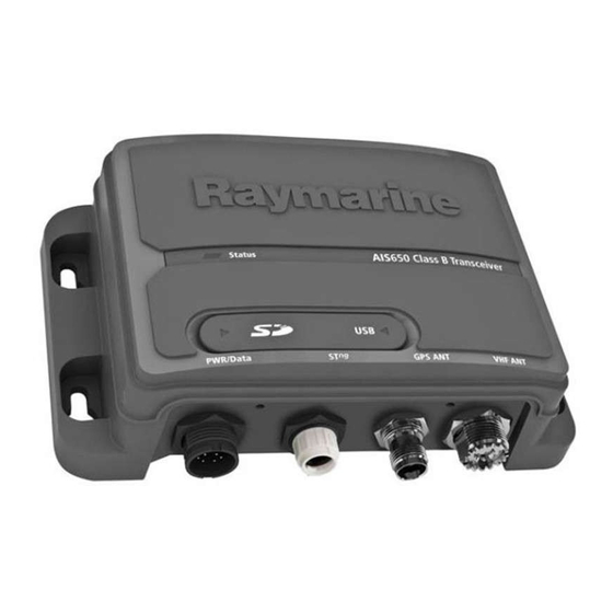
Page 32: Ais650 Class B Transceiver Unit
Mode and will not transmit. However, it will still operate as a receiver. Important: In the United States of America, the MMSI and Static Data must be entered only by a Raymarine dealer or other appropriately qualified installer of marine communications equipment on board vessels.The user is NOT authorized to do... -
Page 33: Requirements For Usa & Canada
2. This device must accept any interference received, including interference that may cause undesired operation. Changes or modifications to this equipment not expressly approved in writing by Raymarine Incorporated could violate compliance with FCC rules and void the operator’s authority to operate the equipment. - Page 34 Le présent appareil est conforme aux CNR d’Industrie Canada You do not need a license to operate this product within sovereign applicables aux appareils radio exempts de licence. L’exploitation waters of Canada or the US. You will need a license to operate est autorisée aux deux conditions suivantes : this radio outside of Canada or the US.
- Page 35 • connected to the radio before transmitting otherwise input any inaccurate data in this device. The MMSI and Static Data must be entered only by a Raymarine dealer or • located where it will be away from people other appropriately qualified installer of marine communications •...
-
Page 36: Requirements For Areas Outside Of Usa & Canada
3.4 Requirements for areas outside of Denmark Norway USA & Canada Estonia Poland Finland Portugal Maritime Mobile Service Identity (MMSI) France Romania A nine-digit Maritime Mobile Service Identity (MMSI) number is required to operate your AIS Transceiver. In some areas, a radio Germany Slovakia operator licence is required before an MMSI number will be issued. -
Page 37: Planning The Installation
3.5 Planning the installation AIS650 system The following illustrations show examples of AIS650 systems. Installation checklist Simple system example Installation includes the following activities: Installation Task Plan your installation. Obtain all required equipment and tools. Mount the system components. Route all cables. Drill cable and mounting holes. - Page 38 Item Description Item Description Multifunction display GPS antenna (supplied with AIS650 transceiver) Vessel’s existing GPS antenna Multifunction display Extended system example Vessel’s existing GPS antenna Note: A Multifunction display connected to the AIS transceiver cannot use the GPS which is connected to the GPS connection on AIS unit.
- Page 39 Pack contents Item Description The AIS650 model contains the following items: 4 x Fixing screws 2 x mounting studs 2 x thumbs nuts 2 m power/data cable Document pack containing: • Installation instruction • Support software CDROM • Warranty registration card SeaTalk Dust cap 1 m SeaTalk...
-
Page 40: Cables And Connections
• Unless otherwise stated use only standard cables of the correct type, supplied by Raymarine. • Ensure that any non-Raymarine cables are of the correct quality and gauge. For example, longer power cable runs may require larger wire gauges to minimize voltage drop along the run. -
Page 41: Connections Overview
3.7 Connections overview Always route data cables as far away as possible from: • other equipment and cables, The transceiver has the following connection types: • high current carrying ac and dc power lines, • antennae. Strain relief Ensure adequate strain relief is provided. Protect connectors from strain and ensure they will not pull out under extreme sea conditions. -
Page 42: Gps Antenna Connection
3.8 GPS antenna connection • Connecting AIS Silent wires • Connecting power The GPS supplied as part of your AIS transceiver system has a fitted 10 m (33ft) cable to connect to the transceiver’s GPS antenna Note: With the SD card / USB cover open the unit will not be connector. -
Page 43: Vhf Connection
3.9 VHF connection Connect up your AIS unit to your vessel’s VHF connections by following the steps found under Connecting RF and Connecting NMEA0183 (low baud rate) below: Connecting RF 1. Connect a dedicated VHF antenna directly to the VHF antenna connector on your AIS unit, or 2. -
Page 44: Multifunction Display Connections
3.10 Multifunction display connections You can connect your AIS unit to a multifunction display using either the dedicated SeaTalk connector or NMEA0183 (high baud rate) via the power/data cable. Follow the steps shown in either: • Connecting NMEA0183 (high baud rate, or •... -
Page 45: Ais Silent Mode Connection
3.11 AIS Silent mode connection Note: The wire colors on your Multifunction display may differ to that shown above if this is the case then ensure you have In addition to enabling AIS silent mode via a connected multifunction connected the correct signals (e.g. IN - on the AIS connects to display. -
Page 46: Power Connection
3.12 Power connection Item Wire color Signal / Description — Bespoke switch Power supply protection Always protect the power supply by connecting the red (positive) Orange AIS Silent + wire to the supply via a 5 A fuse or equivalent automatic circuit Light Green AIS Silent –... - Page 47 • for runs of >1 m (3 ft), use 8 mm (#8 AWG) or greater. Grounding The following requirements apply when grounding Raymarine In any grounding system, always keep the length of connecting equipment which does not have a dedicated drain wire or shield: braid or wires as short as possible.
-
Page 48: Usb Connection
3.13 USB connection The AIS unit includes a Mini-B USB port which provides PC connectivity. To enable connection of the AIS unit to a PC the USB drivers, supplied on the software CDROM must be installed on the PC. Please follow the Installing proAIS2 and USB driver instructions below to install the USB drivers before connecting the AIS unit to a PC. -
Page 49: Installing Proais2 And Usb Drivers
3.14 Installing proAIS2 and USB drivers 3.15 SD Card connection The AIS unit includes a multimedia card reader which allows Before connecting the AIS unit to a PC the proAIS2 application and connection of a SD card up to 2GB in size. USB drivers must be installed. -
Page 50: Location And Mounting
3.16 Location and mounting • Received AIS messages • Own vessel position reports Site requirements • AIS alarm conditions When planning the installation, take the following site requirements • AIS text messages for the AIS transceiver and GPS antenna, into account. •... - Page 51 Unit dimensions Important: The main requirement of the intended location for the GPS antenna is that it gives a good direct line of site to the entire sky, right around the horizon. Ensure that the intended mounting location is: • Open and clear of any obstructions (such as masts, search lights, or other structures) that could block line-of-sight to the sky.
- Page 52 Mounting 5. Place the unit over the screws and move unit down to lock in position Fitting the AIS unit 6. Fully tighten the screws. Note: To ensure water resistance the unit must be mounted Fitting GPS antenna vertically with the connectors facing down. To fit the GPS antenna: Note: If you are fitting the AIS unit to fiberglass that has a gelcoat 1.
- Page 53 remove these tabs before using the cable channel, you could Pole mounting damage the cable. If you want to pole-mount the GPS antenna, obtain a pole of suitable length with a 1 inch 14 TPI thread. 2. Screw the two mounting studs (2) into the underside of the receiver.
-
Page 54: System Checks
This condition remains all the time the transceiver is operating normally and transmitting. Configuration Warning: Configure before use This Raymarine product must be correctly configured, to ensure optimum performance and minimize the chances of unsafe or other erroneous data. Configuration requirement After installation and successful switch on, the AIS transceiver must be configured for optimum performance aboard the vessel. - Page 55 • Type Using AIS • GPS antenna position The exact method of using AIS depends on which type of Raymarine The manner in which configuration is carried out depends on the multifunction display you are using. legal requirements of the geographical area you are.
-
Page 56: Diagnostics
• The VHF antenna lead is securely connected. • The transceiver has not transmitted No vessel data At the relevant Raymarine multifunction display: for more than 2 reporting periods. This could be due to high AIS traffic • Place the cursor over the targeted vessel and ensure or loss of GPS fix. - Page 57 Title Transmit Receive Status indicator Wait at least 30 minutes to check that a ’Quiet time’ has remains amber not been requested by the local authority ● 129793 AIS UTC and Check that the: date report • GPS antenna is properly connected ●...
-
Page 58: Technical Specification
3.20 Technical specification NMEA0183 sentences Sentence Title Transmit Receive Transceiver specification ● AIVDM Received AIS message Waterproofing IPX2 ● AICDO Own vessel AIS Operating temperature range -15˚C to +55˚C (5˚F to 131˚F) report Storage temperature range -20˚C to +75˚C (-4˚F to 167˚F) ●... - Page 59 Connectors • VHF Antenna — SO-239 co-axial connector • GPS antenna — TNC co-axial connector • SeaTalk • NMEA0183 HS — stripped wires • NMEA0183 LS — stripped wires • Power — stripped wires • AIS silent — stripped wires •...
- Page 60 AIS350 / AIS650 Installation instructions...
-
Page 61: Chapter 4 Technical Support
Chapter 4: Technical support Chapter contents • 4.1 Raymarine customer support on page 62 Technical support... -
Page 62: Raymarine Customer Support
4.1 Raymarine customer support Raymarine provides a comprehensive customer support service. You can contact customer support through the Raymarine website, telephone and email. If you are unable to resolve a problem, please use any of these facilities to obtain additional help. -
Page 63: Chapter 5 Options And Accessories
Chapter 5: Options and accessories Chapter contents • 5.1 SeaTalk cables and accessories on page 64 • 5.2 Spares and accessories on page 65 Options and accessories... - Page 64 5.1 SeaTalk cables and accessories Description Part No Notes SeaTalk 5 m (16.4 ft) A06036 SeaTalk cables and accessories for use with compatible products. backbone Description Part No Notes A06037 SeaTalk 20 m (65.6 ft) Backbone Kit A25062 Includes: backbone •...
- Page 65 5.2 Spares and accessories The following spares are available for the AIS receiver / transceiver: Part number Description R62241 GPS antenna — passive (with 10 m coaxial cable) — AIS650 only R32162 2 m power/Data cable Options and accessories...
- Page 66 AIS350 / AIS650 Installation instructions...
Need help?
Do you have a question about the E32158 and is the answer not in the manual?
Questions and answers