Raymarine AIS350 Installation Instructions Manual
Receiver/class b transceiver
Hide thumbs
Also See for AIS350:
- Installation instructions manual (68 pages) ,
- Installation instructions manual (84 pages) ,
- Installation instructions manual (68 pages)

Related Manuals for Raymarine AIS350


Summary of Contents for Raymarine AIS350
- Page 1 AIS 3 5 0 Re c e ive r / AIS 6 5 0 C la s s B Tr a n s c e ive r Ins ta lla tion ins tructions Docume nt numbe r: 87140-1 Da te : 03-2011...
-
Page 3: Docume Nt Numbe R
, SeaTalk and Sportpilot are registered trademarks of Raymarine UK Limited. RayTalk, Seahawk, Smartpilot, Pathfinder and Raymarine are registered trademarks of Raymarine Holdings Limited. FLIR is a registered trademark of FLIR Systems, Inc. and/or its subsidiaries. All other trademarks, trade names, or company names referenced herein are used for identification only and are the property of their respective owners. -
Page 5: Table Of Contents
Classes of AIS..............10 3.6 Cables and connections ..........39 System protocols ............12 3.7 Connections overview ..........40 Chapter 2 AIS350 Receiver ........15 3.8 GPS antenna connection ........... 41 2.1 AIS350 Receiver unit..........16 3.9 VHF connection ............42 2.2 Requirements for USA &... - Page 6 5.1 SeaTalk cables and accessories ......60 5.2 Spares and accessories ..........61 AIS350 / AIS650 Installation instruction...
-
Page 7: Chapter 1 Important Information
It is the user’s responsibility to use official government charts, notices to mariners, caution and proper navigational skill when operating this or any other Raymarine Safety information product. Warning: Product installation and... -
Page 8: General Information
For optimum EMC performance we recommend that wherever Requirement for ferrites on non-Raymarine cables possible: If your Raymarine equipment is to be connected to other equipment • Raymarine equipment and cables connected to it are: using a cable not supplied by Raymarine, a suppression ferrite MUST always be attached to the cable near the Raymarine unit. -
Page 9: Ais Overview
Directive requires the recycling of waste electrical and electronic equipment. Whilst the WEEE Directive does not apply to some Installation guide Raymarine products, we support its policy and ask you to be aware of how to dispose of this product. Information scope... -
Page 10: Classes Of Ais
Class A transceiver, but is not mandatory aboard any vessel. Data Summary Classes of AIS Receiver Transceiver Transceiver The AIS350 is a receiver that receives messages from vessels, Data (receive) (transmit) (receive) land base stations, or aids to navigation (AToNs) carrying Class A Ship’s name... - Page 11 Class A systems Receiver Transceiver Transceiver Data (receive) (transmit) (receive) Ships Dynamic Conditions Reporting rate Time At anchor or moored 3 Minutes Ship’s position 0-14 knots 10 Seconds 0-14 knots and changing course Seconds 14-23 knots 6 Seconds Gyro heading Yes* 14-23 knots and changing course 2 seconds...
-
Page 12: System Protocols
• 9600 baud rate. Used for Navtex. transmit and receive on a single physical bus at any one time, • 38400 baud rate. Used for AIS and other high speed applications. with each node being physically addressable. The standard AIS350 / AIS650 Installation instruction... - Page 13 • The 4800 baud wires connect to the appropriate points on the VHF radio or other NMEA0183 4800 baud input/output device. • The 38400 baud wires connect to appropriate Raymarine multifunction display. The NMEA0183 port on each display connected in this manner must be set to 38400 baud.
- Page 14 AIS350 / AIS650 Installation instruction...
-
Page 15: Chapter 2 Ais350 Receiver
Chapter 2: AIS350 Receiver Chapter contents • 2.1 AIS350 Receiver unit on page 16 • 2.2 Requirements for USA & Canada on page 16 • 2.3 Planning the installation on page 17 • 2.4 Cables and connections on page 20 •... -
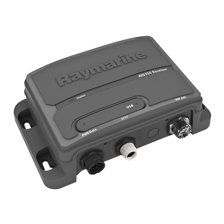
Page 16: Ais350 Receiver Unit
D12126-1 AIS350 Certification details The following information about the receiver is required to complete Industry Canada license applications: • Industry Canada Certification Number: IC:4069B-AIS350 • Output Power: 2 Watts • Modulation: GMSK • Frequency band 1: 161.975 MHz • Frequency band 2: 162.025 MHz... -
Page 17: Planning The Installation
2.3 Planning the installation AIS350 system The following illustrations show examples of AIS350 systems. Installation checklist Simple system example Installation includes the following activities: Installation Task Plan your installation. Obtain all required equipment and tools. Mount the system components. Route all cables. - Page 18 SeaTalk and NMEA0183 at the same time, as data conflicts could occur. Pack contents The AIS350 model contains the following items: S ta tus AIS 350 Re ce ive r S ta tus AIS 350 Re ce ive r...
-
Page 19: Tools Required
SeaTalk Dust cap 1 m SeaTalk spur cable Unpack the AIS unit carefully to prevent damage. Save the carton and packing in case the unit has to be returned for service. Tools required Tools required for installation D12087-1 AIS350 Receiver... -
Page 20: Cables And Connections
Raymarine. Ensure adequate strain relief is provided. Protect connectors from • Ensure that any non-Raymarine cables are of the correct quality strain and ensure they will not pull out under extreme sea conditions. and gauge. For example, longer power cable runs may require larger wire gauges to minimize voltage drop along the run. -
Page 21: Connections Overview
2. Identify the 4800 baud NMEA0183 wires on your VHF set SeaTalk 3. Connect the wires as shown below. VHF antenna Mini—B USB (for PC connectivity) Carry out the following procedures to connect up you receiver: • Connecting VHF • Connecting to Multifunction display. • Connecting power AIS350 Receiver... -
Page 22: Multifunction Display Connections
Note: The wire colors on your VHF may differ to that shown above, if this is the case then ensure you have connected the correct signals (e.g. IN - on the AIS connects to OUT - on your VHF and so on). AIS350 / AIS650 Installation instruction... - Page 23 SeaTalk network as follows: Brown IN + OUT + Orange and i. Connect using SeaTalk 5–way connector. white ii. Connect using a SeaTalk T-Piece connector. iii. Connect using a spare SeaTalk spur on a SeaTalk converter. AIS350 Receiver...
-
Page 24: Power Connection
5 A fuse or equivalent automatic circuit breaker. Grounding The following requirements apply when grounding Raymarine Sharing a breaker equipment which does not have a dedicated drain wire or shield: Where more than 1 piece of equipment shares a breaker you must Common ground point provide protection for the individual circuits. - Page 25 Connect your AIS unit’s power cable to either a 12 V dc or 24 V dc power source as follows: 1. Connect the red wire to the 5 A fuse or equivalent automatic circuit breaker to the supply positive terminal. 2. Connect the black wire to the supply negative terminal. AIS350 Receiver...
-
Page 26: Usb Connection
• Is at least 3 ft (1 m) from an engine, compass or any magnetic device. • Has at least 6 in (100 mm) of clear space below, to allow access for cabling and adequate cable bends. • Is maintained at a temperature between -15°C (5°F) and +55°C (130°F). AIS350 / AIS650 Installation instruction... - Page 27 1. Ensure that the intended installation site meets the conditions described under Site requirements. 2. Using a pencil, offer up the unit and mark the location of the screw holes on the mounting surface. 3. Drill the mounting holes using a 3.2 mm (1/4”) drill bit. AIS350 Receiver...
-
Page 28: System Checks
2. Check that the electronic systems all operate satisfactorily. Using AIS The exact method of using AIS depends on which type of Raymarine multifunction display you are using. Refer to the handbook for your multifunction display for information on using your AIS. -
Page 29: Troubleshooting
• The VHF antenna lead is securely connected. Peak current in normal operation <200mA No vessel data At the relevant Raymarine multifunction display: Average power consumption <2W • Place the cursor over the targeted vessel and ensure the AIS DATA soft key is not set to OFF... - Page 30 280 grams Connectors • VHF Antenna • SeaTalk • NMEA0183 HS — stripped wires • NMEA0183 LS — stripped wires • Power — stripped wires • AIS silent — stripped wires • USB — NMEA0183 AIS350 / AIS650 Installation instruction...
-
Page 31: Chapter 3 Ais650 Class B Transceiver
Chapter 3: AIS650 Class B transceiver Chapter contents • 3.1 AIS650 Class B transceiver unit on page 32 • 3.2 Static data requirement on page 32 • 3.3 Requirements for USA & Canada on page 33 • 3.4 Requirements for areas outside of USA & Canada on page 35 •... -
Page 32: Ais650 Class B Transceiver Unit
Mode and will not transmit. However, it will still operate as a receiver. Important: In the United States of America, the MMSI and Static Data must be entered only by a Raymarine dealer or other appropriately qualified installer of marine communications equipment on board vessels.The user is NOT authorized to do... -
Page 33: Requirements For Usa & Canada
Changes or modifications to this equipment not expressly approved or write: in writing by Raymarine Incorporated could violate compliance with FCC rules and void the operator’s authority to operate the Industry Canada Radio Regulatory Branch equipment. - Page 34 The MMSI • FCC Type Number: FCC:PJ5–AIS650 and Static Data must be entered only by a Raymarine dealer or other appropriately qualified installer of marine communications • FCC Type Accepted: Parts 15 and 80 equipment on board vessels.
-
Page 35: Requirements For Areas Outside Of Usa & Canada
3.4 Requirements for areas outside of Warning: Maximum Permissible USA & Canada Exposure Failure to observe these guidelines may expose those Maritime Mobile Service Identity (MMSI) within the maximum permissible exposure (MPE) radius to RF radiation absorption that exceeds the A nine-digit Maritime Mobile Service Identity (MMSI) number is FCC MPE limit. -
Page 36: Planning The Installation
Switzerland Drill cable and mounting holes. Italy Turkey Make all connections to equipment. Latvia United Kingdom Secure all equipment in place. Complete the post-installation check. AIS650 system The following illustrations show examples of AIS650 systems. AIS350 / AIS650 Installation instruction... - Page 37 Simple system example Extended system example ta tus AIS 650 Cla s s B Tra ns ce ive r US B P WR/Da ta GP S ANT VHF ANT AIS 650 Cla s s B Tra ns ce ive r ta tus US B P WR/Da ta...
- Page 38 VHF ANT SeaTalk Dust cap 1 m SeaTalk spur cable Unpack the unit and GPS carefully to prevent damage. Save the carton and packing in case the unit has to be returned for service. D12096-1 AIS350 / AIS650 Installation instruction...
-
Page 39: Cables And Connections
• Unless otherwise stated use only standard cables of the correct type, supplied by Raymarine. • Ensure that any non-Raymarine cables are of the correct quality and gauge. For example, longer power cable runs may require larger wire gauges to minimize voltage drop along the run. -
Page 40: Connections Overview
Carry out the following procedures to connect up you transceiver: shielding is intact (e.g. hasn’t been scraped off by being squeezed through a tight area). • Connecting GPS • Connecting VHF • Connecting to Multifunction display. AIS350 / AIS650 Installation instruction... -
Page 41: Gps Antenna Connection
3.8 GPS antenna connection • Connecting AIS Silent wires • Connecting power The GPS supplied as part of your AIS transceiver system has a fitted 10 m (33ft) cable to connect to the transceiver’s GPS antenna connector. Connect the cable from the GPS antenna to the GPS connector on the underside of the AIS transceiver. -
Page 42: Vhf Connection
Note: The wire colors on your VHF may differ to that shown above, if this is the case then ensure you have connected the correct signals (e.g. IN - on the AIS connects to OUT - on your VHF and so on). AIS350 / AIS650 Installation instruction... -
Page 43: Multifunction Display Connections
3.10 Multifunction display connections US B GP S ANT VHF ANT WR/Da ta You can connect your AIS unit to a multifunction display using either the dedicated SeaTalk connector or NMEA0183 (high baud rate) via the power/data cable. Follow the steps shown in either: •... -
Page 44: Ais Silent Mode Connection
SeaTalk network as follows: i. Connect using SeaTalk 5–way connector. D12091-1 ii. Connect using a SeaTalk T-Piece connector. iii. Connect using a spare SeaTalk spur on a SeaTalk converter. AIS350 / AIS650 Installation instruction... -
Page 45: Power Connection
3.12 Power connection Item Wire color Signal / Description — Bespoke switch Power supply protection Orange AIS Silent + Always protect the power supply by connecting the red (positive) Green AIS Silent – wire to the supply via a 5 A fuse or equivalent automatic circuit breaker. - Page 46 • for runs of >1 m (3 ft), use 8 mm (#8 AWG) or greater. Grounding The following requirements apply when grounding Raymarine In any grounding system, always keep the length of connecting equipment which does not have a dedicated drain wire or shield: braid or wires as short as possible.
-
Page 47: Usb Connection
3.13 USB connection US B GP S ANT VHF ANT WR/Da ta The AIS unit includes a Mini-B USB port which provides PC connectivity. To enable connection of the AIS unit to a PC the USB drivers, supplied on the software CDROM must be installed on the The USB port can be used to: •... -
Page 48: Sd Card Connection
6. If the configuration fails the LED status indicator shall flash RED 5 times. Recording voyage data To record voyage data to SD card follow the steps below: 1. Insert a blank SD card into your AIS units SD card reader. AIS350 / AIS650 Installation instruction... -
Page 49: Location And Mounting
3.15 Location and mounting Important: The main requirement of the intended location for the GPS antenna is that it gives a good direct line of site to the entire sky, right around the horizon. Site requirements When planning the installation, take the following site requirements Ensure that the intended mounting location is: for the AIS transceiver and GPS antenna, into account. - Page 50 Site requirements. 2. Using a pencil, offer up the unit and mark the location of the screw holes on the mounting surface. 3. Drill the mounting holes using a 3.2 mm (1/4”) drill bit. AIS350 / AIS650 Installation instruction...
- Page 51 4. Part fit the screws. remove these tabs before using the cable channel, you could damage the cable. 5. Place the unit over the screws and move unit down to lock in position 6. Fully tighten the screws. Fitting GPS antenna To fit the GPS antenna: 1.
- Page 52 4. Route the antenna cable as follows: i. If you want to route the antenna cable directly down from the antenna (option A), feed it through the center of the pole mount adaptor and then down through the pole. AIS350 / AIS650 Installation instruction...
-
Page 53: System Checks
You can use the supplied ProAIS PC software, to check the vessel This condition remains all the time the transceiver is operating data programmed into your AIS transceiver. If this information is normally and transmitting. incorrect please contact your Raymarine dealer before using the transceiver. Configuration Areas outside of USA... -
Page 54: Diagnostics
2. Check that the electronic systems all operate satisfactorily. Using AIS LED Status indicator The exact method of using AIS depends on which type of Raymarine LED Status indicator multifunction display you are using. The LED STATUS indicator on the transceiver provides an indication Refer to the handbook for your multifunction display for information of product status. -
Page 55: Troubleshooting
• The MMSI number has been properly configured (use the proAIS application) No vessel data At the relevant Raymarine multifunction display: • Place the cursor over the targeted vessel and ensure the AIS DATA soft key is not set to OFF •... -
Page 56: Technical Specification
Receiver channels • 5A Nominal time to first fix 36 seconds 156.025 MHz to 162.025 MHz Operating frequency range Channel spacing 25 KHz Transmitter 1 transmitter Receiver sensitivity –107 dBm Receivers 2 receivers Weight 285 grams AIS350 / AIS650 Installation instruction... -
Page 57: Chapter 4 Technical Support
Chapter 4: Technical support Chapter contents • 4.1 Raymarine customer support on page 58 Technical support... -
Page 58: Raymarine Customer Support
4.1 Raymarine customer support Raymarine provides a comprehensive customer support service. You can contact customer support through the Raymarine website, telephone and email. If you are unable to resolve a problem, please use any of these facilities to obtain additional help. -
Page 59: Chapter 5 Options And Accessories
Chapter 5: Options and accessories Chapter contents • 5.1 SeaTalk cables and accessories on page 60 • 5.2 Spares and accessories on page 61 Options and accessories... - Page 60 A06041 SeaTalk 5 m (16.4 ft) SeaTalk Inline spur terminator SeaTalk 0.4 m (1.3 ft) A06033 SeaTalk Blanking plug A06032 backbone SeaTalk 1 m (3.3 ft) A06034 backbone SeaTalk 3 m (9.8 ft) A06035 backbone AIS350 / AIS650 Installation instruction...
- Page 61 5.2 Spares and accessories The following spares are available for the AIS receiver / transceiver: Part number Description R32161 GPS antenna — passive (with 10 m coaxial cable) — AIS650 only R32162 2 m power/Data cable Options and accessories...
- Page 62 AIS350 / AIS650 Installation instruction...
- Page 64 www.ra ym a rin e .c o m...
Need help?
Do you have a question about the AIS350 and is the answer not in the manual?
Questions and answers