Advertisement
Table of Contents
- 1 General Information
- 2 Product Disposal
- 3 Warranty Registration
- 4 IMO and SOLAS
- 5 Technical Accuracy
- 6 Parts Supplied
- 7 Installation Overview
- 8 Required Additional Components
- 9 Cable Identification
- 10 Antenna Installation
- 11 Verify Operation
- 12 Troubleshooting
- 13 Specifications
- Download this manual
Advertisement
Table of Contents

Related Manuals for Raymarine SiriusXM SR200


Summary of Contents for Raymarine SiriusXM SR200
- Page 1 SR200 SiriusXM InfoLINK Weather & Audio Receiver Installation instructions English (en-US) Date: 06-2019 Document number: 87320-3 © 2019 Raymarine UK Limited & Sirius XM Radio Inc.
- Page 2 Thank you for purchasing the SiriusXM InfoLINK Receiver Tracking of weather is easier than ever with the SiriusXM InfoLINK Receiver for Raymarine MFD’s. Raymarine and SiriusXM have teamed up to bring you live, up-to-date weather information and forecasting to give you peace of mind, no matter when or how you are using your boat.
- Page 3 Software Updates Important: Check the Raymarine website for the latest software releases for your product, www.raymarine.com/software. Product Handbooks The latest versions of all English and translated handbooks are available to download in PDF format from the website www.raymarine.com. Please check the website to ensure you have the latest handbooks.
-
Page 4: General Information
- At least 1 m (3 ft) from any equipment occur if the product is subjected to commercial transmitting or cables carrying radio signals high-pressure washing. Raymarine will not warrant e.g. VHF radios, cables and antennas. In the products subjected to high-pressure washing. -
Page 5: Product Disposal
IMO and SOLAS Requirement for ferrites on non-Raymarine cables The equipment described within this document If your Raymarine equipment is to be connected is intended for use on leisure marine boats and to other equipment using a cable not supplied by... -
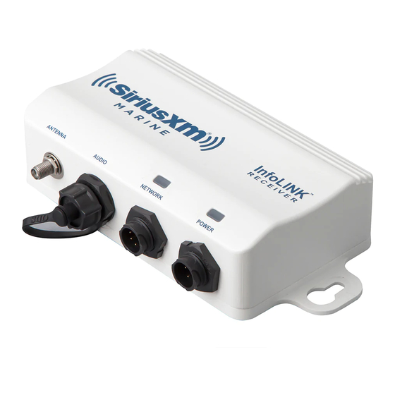
Page 6: Parts Supplied
Parts Supplied SiriusXM Receiver Raymarine MFD SiriusXM to Raymarine Network Cable InfoLINK R E C E I V E R M A R I N E ANTENNA AUDIO NETWORK POWER SiriusXM Stereo Audio Cable SiriusXM Marine InfoLINK™ Receiver SiriusXM Power Cable Shakespeare ®... -
Page 7: Installation Overview
Multifunction display hardware and software compatibility For compatibility information visit raymarine.com/weather. Installation Overview InfoLINK MULTIFUNCTION DISPLAY Shown at right is a typical installation RECEIVER overview for the InfoLINK Receiver in a ® Raymarine system. InfoLINK R E C E I V E R... -
Page 8: Required Additional Components
Required for Component / Service SiriusXM Satellite Radio SiriusXM Marine Weather Sirius SRA-40 type-approved antenna Compatible Raymarine multifunction display GPS receiver — provides position information for your vessel in the weather, chart and radar applications. Some multifunction displays have an internal GPS receiver. -
Page 9: Cable Identification
Cable Identification The following is the pin identification for the Data Cable provided with the InfoLINK Receiver. SiriusXM Receiver Raymarine MFD SiriusXM Raymarine Description Description Connector Connector Ethernet RX+ (White/Green) Ethernet TX+(White/Orange) Ethernet RX– (Green) Ethernet TX– (Orange) Ethernet TX+(White/Orange) Not Used Ethernet TX–... - Page 10 • A80005: 5m (16.4ft) RayNet (female to female) cable. • A62362: 10m (32.8ft) RayNet (female to female) cable. • A80006: 20m (65.6ft) RayNet (female to female) cable. Note: if a longer network connection is needed, visit www.raymarine.com for additional Raynet to Raynet extension solutions.
- Page 11 The following is the pin and wire identification for the Power Cable provided with the InfoLINK Receiver. Power Wire Description Description Connector Color Battery + (Switched) Battery + (Switched) Ground - Black Ground - RF Shield Ground White RF Shield Ground The following is the pin and connector identification for the Audio Cable provided with the InfoLINK Receiver.
- Page 12 InfoLINK Receiver Installation Connect the Power Cable The InfoLINK Receiver should be connected to a 12 Select a mounting location for the InfoLINK Receiver or 24 volt power source, negative ground. that is sheltered from the elements. While the Caution: Some vessels may have a positive ground receiver is water resistant, it should be mounted system.
- Page 13 If in doubt consult an authorized • Each unit should have its own dedicated Raymarine dealer. power cable wired back to the distribution panel. Connect the Power Cable to the POWER connection of the receiver.
- Page 14 If you are not installing an audio connection, do not connectors. remove the water resistant cap that is installed on If your Raymarine system does not utilize a Network the InfoLINK Receiver’s AUDIO connector. Switch, connect the Raymarine end of the cable to The Audio Cable provides an RCA-style Left and the Raymarine MFD’s RayNet (Ethernet) port.
-
Page 15: Antenna Installation
Antenna Installation Caution: When installing the antenna, do not cut or alter the antenna cable, or remove the cable connectors. Two considerations are necessary before installing the antenna. First, finding a suitable mounting location, and second determine how the antenna will be mounted. There are several in-box mounting options for the antenna, or accessories can be purchased from marine stores for additional mounting options. - Page 16 Choose a Mounting Option In-Box Mounting Options Surface Mount Antenna secured from the underside of the mounting surface. For mounting surfaces between 1/4” and 1” thick, use the supplied extension shaft. Route antenna cable through the mounting surface. Secure from below mounting surface using the mounting lock washer &...
- Page 17 Installing the Antenna Follow the instructions in the next sections for the mounting method you’ve selected. Do not cut the In-box antenna mounting options are surface mount, 6” antenna lead or remove the connectors from low-profile surface mount, or pedestal mount. any of the cables under any circumstances.
- Page 18 that was drilled. center hole for the antenna cable. When drilling fiberglass surfaces, use a small backup 4. Apply a small bead of marine sealant around block of scrap wood to control push-through the outer edge of the antenna base to insure a splintering.
- Page 19 5. Either pass the 6” antenna lead along with the connector through the center hole, or, lay the 6” antenna lead into the cable opening in the Antenna base gasket. Place the antenna, base, and base gasket on the mounting surface aligning it to Mounting Holes the marks made in step 3.
- Page 20 b. Align the base with the antenna, the base o-ring in place. gasket, and the pedestal top so that the 7. If you are not routing the 6” antenna lead openings for the 4 screws are aligned, and out through the side of the pedestal bottom, use the provided screws to screw them continue with step 9.
- Page 21 out through the side of the pedestal bottom, Rail Mount make sure the antenna lead can turn freely so The center hole in ratchet-type antenna mounts that it does not get twisted as you screw the will not accommodate the SRA-50’s connector. You antenna assembly onto the pedestal bottom.
-
Page 22: Verify Operation
(blue), and that the Network LED light is randomly these steps: flashing green, which indicates normal network 1. Make sure the Raymarine system is turned on. traffic. Verify that you are receiving the SiriusXM signal by entering the SiriusXM menu in your MFD. -
Page 23: Troubleshooting
Troubleshooting The troubleshooting information in this section is for general reference. Consult the documentation that accompanied your Raymarine system for specific operating instructions and advisory messages that may be displayed. LED Indicator Lights The InfoLINK Receiver has two LED indicator lights which show the current state of the receiver. - Page 24 InfoLINK Receiver. Visit the Web customer support area at: Antenna Cable Replace the antenna and antenna www.raymarine.com for FAQs, servicing information Shorted cable. and support. Check Tuner Network Cable is not connected (Chek Tuner, Chk to the MFD or network switch.
-
Page 25: Specifications
Specifications FCC Statement The user is cautioned that changes or modifications not expressly approved by Sirius XM Radio Inc. can void the user’s authority to operate InfoLINK Receiver this device. This device complies with Part 15 of the FCC Rules. Operation is Dimensions . - Page 26 Copyrights and Trademarks Raymarine Legal Information Raymarine by FLIR and related marks are property of Raymarine UK Limited. All Rights Reserved. Shakespeare Legal Information Shakespeare and related marks are property of Shakespeare Company, LLC. All Rights Reserved.
- Page 27 Registration To register your Raymarine product ownership, please visit www.raymarine.com and register online. It is important that you register your product to receive full warranty benefits. Your unit package includes a bar code label indicating the serial number of the unit.
- Page 28 Raymarine Inc. 9 Townsend West, Nashua, NH, 03063. United States. Tel: (+1) 603-324-7900 www.raymarine.com a brand by...
Need help?
Do you have a question about the SiriusXM SR200 and is the answer not in the manual?
Questions and answers