
Related Manuals for Daikin VRV FXMQ50P7VEB9


Summary of Contents for Daikin VRV FXMQ50P7VEB9
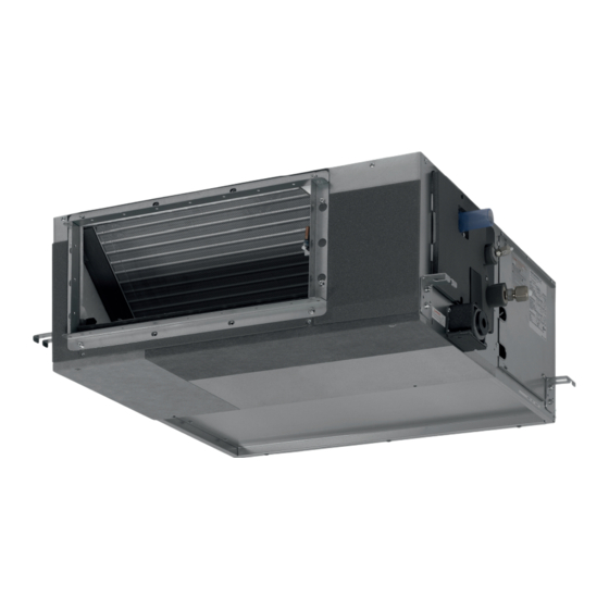
- Page 1 INSTALLATION AND OPERATION MANUAL System air conditioners FXMQ50P7VEB9 FXMQ63P7VEB9 FXMQ80P7VEB9 FXMQ100P7VEB9 FXMQ125P7VEB9...
- Page 2 ≥300 <45 ≤300 mm 1~1.5 m...
- Page 3 3P468238-4...
-
Page 4: Table Of Contents
OTHER DAMAGE TO THE EQUIPMENT. BE SURE ONLY fire. TO USE ACCESSORIES MADE BY DAIKIN WHICH ARE ■ This appliance is not intended for use by persons, including SPECIFICALLY DESIGNED FOR USE WITH THE... -
Page 5: Important Information Regarding The Refrigerant Used
Optional accessories ELECTING INSTALLATION SITE ■ There are two types of remote controllers: wired and wireless. (See figure 1 figure Select a remote controller according to customer request and install in an appropriate place. Select an installation site where the following conditions are Refer to catalogues and technical literature for selecting a fulfilled and that meets your customer's approval. -
Page 6: Preparations Before Installation
Duct service opening Interchangeable plate For other installation than standard installation, contact NOTE your Daikin dealer for details. Installation with rear duct and duct service opening (See figure 6b) The fan speed for this indoor unit is preset to provide standard external static pressure. -
Page 7: Indoor Unit Installation
■ Refer to Table 1 for the dimensions of flare nut spaces and the NDOOR UNIT INSTALLATION appropriate tightening torque. (Overtightening may damage the flare and cause leaks.) When installing optional accessories (except for the air inlet panel), Table 1 read also the installation manual of the optional accessories. -
Page 8: Drain Piping Work
Cautions for brazing Wrap the supplied large sealing pad over the metal clamp and drain hose to insulate and fix it with clamps. ■ Be sure to carry out a nitrogen blow when brazing. Insulate the complete drain piping inside the building (field Brazing without carrying out nitrogen replacement or releasing supply). -
Page 9: Electric Wiring Work
LECTRIC WIRING WORK Caution for drain socket Do not remove the drain pipe plug. Water might leak out. General instructions The drain outlet is only used to discharge water if the drain pump is not used or before maintenance. Gently put in and ■... -
Page 10: Wiring Example And How To Set The Remote Controller
Specifications for field supplied fuses and wire When connecting wires of the same gauge, connect them according to the figure. Power supply wiring Model Field fuses Wire Size 20~125 16 A H05VV-U3G Local codes Model Wire Size Use the specified electric wire. Connect the wire securely to the terminal. -
Page 11: Wiring Example
IRING EXAMPLE IELD SETTING Field setting must be made on the remote controller in function of the Fit the power supply wiring of each unit with a switch and fuse as installation condition. shown in figure ■ Setting can be made by changing the "Mode number", "First Power supply code No."... - Page 12 External static pressure settings ■ If there is no change after airflow adjustment in the Settings for external static pressure can be achieved in 2 ways: ventilation paths, be sure to perform setting the automatic airflow adjustment again. Using the airflow automatic adjustment function ■...
-
Page 13: Installation Of The Decoration Panel
Computerised control (forced off and on/off operation) EST OPERATION Wire specifications and how to perform wiring Refer to the installation manual of the outdoor unit. Connect input from outside to terminals T1 and T2 of the The operation lamp of the remote controller will flash when an error terminal board (remote controller to transmission wiring). -
Page 14: Disposal Requirements
If chains are present, unhook the chains. Shut the air inlet grille. (Only for bottom suction.) Refer to item no. 1. After turning on the power, press FILTER SIGN RESET button. The "TIME TO CLEAN AIR FILTER" display is turned off. How to clean air outlet and outside panels ■... -
Page 15: Wiring Diagram
IRING DIAGRAM : FIELD WIRING : BLACK : ORANGE : CONNECTOR : BLUE : PINK : WIRE CLAMP : BROWN : RED : PROTECTIVE EARTH (SCREW) : GREEN : WHITE : LIVE : GREY : YELLOW : NEUTRAL A1P......PRINTED CIRCUIT BOARD R3T ...... - Page 19 Control box IN/D OUT/D Control box OUT/D IN/D Control box IN/D OUT/D Control box IN/D OUT/D SETTING...
- Page 20 3P468515-4 12.2016...
Need help?
Do you have a question about the VRV FXMQ50P7VEB9 and is the answer not in the manual?
Questions and answers