Sign In
Upload
Manuals
Brands
GW Instek Manuals
Test Equipment
MSO-2000EA
GW Instek MSO-2000EA Oscilloscope Manuals
Manuals and User Guides for GW Instek MSO-2000EA Oscilloscope. We have
2
GW Instek MSO-2000EA Oscilloscope manuals available for free PDF download: User Manual
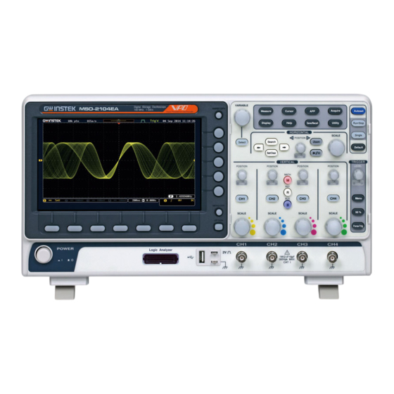
GW Instek MSO-2000EA User Manual (354 pages)
Mixed-Signal Oscilloscope
Brand:
GW Instek
| Category:
Test Equipment
| Size: 13 MB
Table of Contents
Table of Contents
3
Safety Instructions
7
Etting Started
12
Getting Started
13
MSO-2000E/2000EA Series Overview
14
Integrated Instruments and Series Lineup
14
Main Features
15
Accessories
16
Appearance
18
MSO-2000E/2000EA 4-Channel Models Front Panel
18
MSO-2000E/2000EA 2-Channel Models Front Panel
19
MSO-2000E Rear Panel
26
MSO-2000EA Rear Panel
26
Display
28
Set up
31
Tilt Stand
31
Power up
32
First Time Use
33
How to Use this Manual
36
Built-In Help
41
Easurement
42
Measurement
42
Basic Measurement
43
Channel Activation
43
Autoset
44
Run/Stop
46
Horizontal Position/Scale
47
Vertical Position/Scale
49
Automatic Measurement
50
Add Measurement
54
Remove Measurement
57
Gated Mode
57
Display All Mode
58
High Low Function
59
Statistics
61
Reference Levels
63
Cursor Measurement
65
Use Horizontal Cursors
65
Use Vertical Cursors
69
Math Operation
73
Basic Math Overview & Operators
73
Addition/Subtraction/Multiplication/Division
73
FFT Overview & Window Functions
75
FFT Operation
76
Advanced Math Overview
78
Advanced Math Operation
79
Dvanced Configuration
83
Advanced Configuration
83
Acquisition
86
Select Acquisition Mode
86
Show Waveform in XY Mode
87
Set the Record Length
89
Segmented Memory Acquisition
91
Segments Display
93
Set the Number of Segments
94
Run Segmented Memory
95
Navigate Segmented Memory
97
Play through each Segment
97
Measurement on Segments
98
Segment Info
102
Display
103
Display Waveform as Dots or Vectors
103
Set the Level of Persistence
103
Set the Intensity Level
104
Select Display Graticule
105
Freeze the Waveform (Run/Stop)
106
Turn off Menu
107
Horizontal View
108
Move Waveform Position Horizontally
108
Select Horizontal Scale
109
Select Waveform Update Mode
110
Zoom Waveform Horizontally
111
Play/Pause
113
Vertical View (Channel)
116
Move Waveform Position Vertically
116
Select Vertical Scale
117
Select Coupling Mode
117
Input Impedance
118
Invert Waveform Vertically
118
Limit Bandwidth
119
Expand by Ground/Center
120
Select Probe Type
121
Select Probe Attenuation Level
122
Set the Deskew
122
Bus Key Configuration
124
Bus Display
124
Serial Bus Overview
126
UART Serial Bus Configuration
128
C Serial Bus Interface
130
SPI Serial Bus Interface
132
CAN Serial Bus Interface
134
LIN Serial Bus Interface
136
Parallel Bus
138
Bus Decoding
140
Threshold Configuration
140
Serial or Parallel Bus Event Tables
142
Event Tables Format
146
Adding a Label to a Bus
147
Using Cursors with the Serial or Parallel Bus
149
Trigger
151
Trigger Type Overview
151
Trigger: Types and Sources
153
Trigger Parameter Overview
154
Setup Holdoff Level
161
Setup Trigger Mode
162
Using the Edge Trigger
162
Using Advanced Delay Trigger
164
Using Pulse Width Trigger
166
Using Video Trigger
169
Pulse Runt Trigger
170
Using Rise and Fall Trigger
172
Using the Timeout Trigger
173
Using the Bus Trigger
176
UART BUS Trigger Settings
176
I 2 C Bus Trigger Settings
177
SPI Bus Trigger Settings
181
CAN Bus Trigger
182
LIN Bus Trigger
185
Parallel Bus Trigger
187
Using the Logic Trigger
188
Search
193
Configuring Search Events
193
Copying Search Event To/From Trigger Events
195
Search Event Navigation
195
Save Search Marks
196
Setting/Clearing Single Search Events
197
FFT Peak
198
System Settings and Miscellaneous Settings
202
Select Menu Language
202
View System Information
203
Erase Memory
203
Set Date and Time
204
Probe Compensation Frequency
205
QR Code Reader Function
205
Ogic Analyzer
207
Logic Analyzer
207
Logic Analyzer Operation
208
Overview
208
Using the Logic Analyzer Probes
209
Digital Display Overview
210
Activating Digital Channels
211
Activate Digital Channels as a Group
211
Activate Individual Channels
212
Moving the Digital Channels or Creating Digital Channel Groups
213
Digital Channel Vertical Scale
217
Digital Channel Threshold Levels
217
Analog Waveform
219
Adding Labels to Digital Channels or the Analog Waveform
220
Rbitrary Wave Generator
223
Arbitrary Wave Generator
223
Arbitrary Wave Generator Operation
224
Overview
224
Rear Panel
225
AWG Display Overview
226
Generator Connection
226
Output Setup
227
Select the Active Channel
227
Setting the Phase
228
GEN1 and GEN2 Setup
229
Turn the Output on for the Selected Channel
228
Setting the Load Impedance
228
Selecting a Waveform
229
Waveform Settings
230
AM Modulation
233
FM Modulation
235
FSK Modulation
237
Sweep
239
Manage Arbitrary Waveforms
241
Create New ARB Waveform
241
Edit an Existing ARB Waveform
243
Load ARB Waveform
250
Save ARB Waveform
252
Coupling and Tracking Waveforms Settings
254
Pplications
258
Applications
259
Introduction
259
Overview
259
Running Applications
260
Go-Nogo Application
261
DVM Application
266
Data Log Application
268
Digital Filter Application
270
Mask Application
272
Select the Source Channel
272
Configure the Mask Violation
273
Auto Mask
274
User Defined Mask / Create Mask
277
User-Defined Mask File Format
280
Ave/Recall
282
Save/Recall
282
File Format/Utility
283
Image File Format
283
Waveform File Format
283
Spreadsheet File Format
284
Setup File Format
286
Create/Edit Labels
289
Save
292
File Type/Source/Destination
292
Save Image
293
Save Waveform
295
Save Setup
297
Recall
300
File Type/Source/Destination
300
Recall Default Panel Setting
301
Recall Waveform
303
Recall Setup
304
Reference Waveforms
306
Recall and Display Reference Waveforms
306
Ile Utilities
308
File Utilities
308
File Navigation
309
Create Folder
311
Rename File
312
Delete File or Folder
313
Copy File to USB
314
Hardcopy Key
315
Remote Control Config
319
Interface Configuration
320
Configure USB Interface
320
USB Functionality Check
321
Configure the Ethernet Interface
322
Configure Socket Server
324
Socket Server Functionality Check
325
Maintenance
331
Faq
336
Appendix
339
Updating the Firmware
340
MSO-2000E/2000EA Specifications
342
Model-Specific
342
Common
343
Probe Specifications
347
Dimensions
349
Declaration of Conformity
350
Index
351
Advertisement
GW Instek MSO-2000EA User Manual (351 pages)
Mixed-Signal Oscilloscope
Brand:
GW Instek
| Category:
Test Equipment
| Size: 11 MB
Table of Contents
Table of Contents
3
Safety Instructions
6
Etting Started
11
Getting Started
11
Integrated Instruments and Series Lineup
12
MSO-2000E/2000EA Series Overview
12
Main Features
13
Accessories
14
Appearance
16
MSO-2000E/2000EA 4-Channel Models Front Panel
16
MSO-2000E/2000EA 2-Channel Models Front Panel
17
MSO-2000E Rear Panel
24
MSO-2000EA Rear Panel
24
Display
26
Set up
29
Tilt Stand
29
Power up
30
First Time Use
31
How to Use this Manual
34
Built-In Help
39
Easurement
40
Measurement
40
Basic Measurement
41
Channel Activation
41
Autoset
42
Run/Stop
44
Horizontal Position/Scale
45
Vertical Position/Scale
47
Automatic Measurement
48
Add Measurement
52
Gated Mode
55
Remove Measurement
55
Display All Mode
56
High Low Function
57
Statistics
59
Reference Levels
61
Cursor Measurement
63
Use Horizontal Cursors
63
Use Vertical Cursors
67
Addition/Subtraction/Multiplication/Division
71
Basic Math Overview & Operators
71
Math Operation
71
FFT Overview & Window Functions
73
FFT Operation
74
Advanced Math Overview
76
Advanced Math Operation
77
Dvanced Configuration
81
Advanced Configuration
81
Acquisition
84
Select Acquisition Mode
84
Show Waveform in XY Mode
85
Set the Record Length
87
Segmented Memory Acquisition
89
Segments Display
91
Set the Number of Segments
92
Run Segmented Memory
93
Navigate Segmented Memory
95
Play through each Segment
95
Measurement on Segments
96
Segment Info
100
Display
101
Display Waveform as Dots or Vectors
101
Set the Level of Persistence
101
Set the Intensity Level
102
Select Display Graticule
103
Freeze the Waveform (Run/Stop)
104
Turn off Menu
105
Horizontal View
106
Move Waveform Position Horizontally
106
Select Horizontal Scale
107
Select Waveform Update Mode
108
Zoom Waveform Horizontally
109
Play/Pause
111
Move Waveform Position Vertically
114
Vertical View (Channel)
114
Select Coupling Mode
115
Select Vertical Scale
115
Input Impedance
116
Invert Waveform Vertically
116
Limit Bandwidth
117
Expand by Ground/Center
118
Select Probe Type
119
Select Probe Attenuation Level
120
Set the Deskew
120
Bus Display
122
Bus Key Configuration
122
Serial Bus Overview
124
UART Serial Bus Configuration
126
I 2 C Serial Bus Interface
128
SPI Serial Bus Interface
130
CAN Serial Bus Interface
132
LIN Serial Bus Interface
133
Parallel Bus
135
Bus Decoding
137
Threshold Configuration
137
Serial or Parallel Bus Event Tables
139
Event Tables Format
143
Adding a Label to a Bus
144
Using Cursors with the Serial or Parallel Bus
146
Trigger
148
Trigger Type Overview
148
Trigger: Types and Sources
150
Trigger Parameter Overview
151
Setup Holdoff Level
158
Setup Trigger Mode
159
Using the Edge Trigger
159
Using Advanced Delay Trigger
161
Using Pulse Width Trigger
163
Using Video Trigger
166
Pulse Runt Trigger
167
Using Rise and Fall Trigger
169
Using the Timeout Trigger
170
UART BUS Trigger Settings
173
Using the Bus Trigger
173
I 2 C Bus Trigger Settings
174
SPI Bus Trigger Settings
177
CAN Bus Trigger
179
LIN Bus Trigger
182
Parallel Bus Trigger
184
Using the Logic Trigger
185
Configuring Search Events
190
Search
190
Copying Search Event To/From Trigger Events
192
Search Event Navigation
192
Save Search Marks
193
Setting/Clearing Single Search Events
194
FFT Peak
195
Select Menu Language
199
System Settings and Miscellaneous Settings
199
Erase Memory
200
View System Information
200
Set Date and Time
201
Probe Compensation Frequency
202
QR Code Reader Function
202
Ogic Analyzer
204
Logic Analyzer
204
Logic Analyzer Operation
205
Overview
205
Using the Logic Analyzer Probes
206
Digital Display Overview
207
Activate Digital Channels as a Group
208
Activating Digital Channels
208
Activate Individual Channels
209
Moving the Digital Channels or Creating Digital Channel Groups
210
Digital Channel Threshold Levels
214
Digital Channel Vertical Scale
214
Analog Waveform
216
Adding Labels to Digital Channels or the Analog Waveform
217
Rbitrary Wave Generator
220
Arbitrary Wave Generator
220
Arbitrary Wave Generator Operation
221
Overview
221
Rear Panel
222
AWG Display Overview
223
Generator Connection
223
Output Setup
224
Select the Active Channel
224
Setting the Load Impedance
225
Setting the Phase
225
Turn the Output on for the Selected Channel
225
GEN1 and GEN2 Setup
226
Selecting a Waveform
226
Waveform Settings
227
AM Modulation
230
FM Modulation
232
FSK Modulation
234
Sweep
236
Create New ARB Waveform
238
Manage Arbitrary Waveforms
238
Edit an Existing ARB Waveform
240
Load ARB Waveform
247
Save ARB Waveform
249
Coupling and Tracking Waveforms Settings
251
Pplications
255
Applications
255
Introduction
256
Overview
256
Running Applications
257
Go-Nogo Application
258
DVM Application
263
Data Log Application
265
Digital Filter Application
267
Mask Application
269
Select the Source Channel
269
Configure the Mask Violation
270
Auto Mask
271
User Defined Mask / Create Mask
274
User-Defined Mask File Format
278
Ave/Recall
279
Save/Recall
279
File Format/Utility
280
Image File Format
280
Waveform File Format
280
Spreadsheet File Format
281
Setup File Format
283
Create/Edit Labels
286
File Type/Source/Destination
289
Save
289
Save Image
290
Save Waveform
292
Save Setup
294
File Type/Source/Destination
297
Recall
297
Recall Default Panel Setting
298
Recall Waveform
300
Recall Setup
301
Recall and Display Reference Waveforms
303
Reference Waveforms
303
Ile Utilities
305
File Utilities
305
File Navigation
306
Create Folder
308
Rename File
309
Delete File or Folder
310
Copy File to USB
311
Hardcopy Key
312
Remote Control Config
316
Configure USB Interface
317
Interface Configuration
317
USB Functionality Check
318
Configure the Ethernet Interface
319
Configure Socket Server
321
Socket Server Functionality Check
322
Maintenance
327
Faq
333
Appendix
337
Updating the Firmware
337
Model-Specific
339
MSO-2000E/2000EA Specifications
339
Common
340
Gtp-070B-4
344
Gtp-100B-4
344
Probe Specifications
344
Gtp-200B-4
345
Dimensions
346
Declaration of Conformity
347
Advertisement
Related Products
GW Instek MSO-2000E
GW Instek MSO-2074EA
GW Instek MSO-2072EA
GW Instek MSO-2072E
GW Instek MSO-2074E
GW Instek MSO-2202EA
GW Instek MSO-2104EA
GW Instek MSO-2102E
GW Instek MSO-2204EA
GW Instek MSO-2104E
GW Instek Categories
Test Equipment
Power Supply
Measuring Instruments
Multimeter
Inverter
More GW Instek Manuals
Login
Sign In
OR
Sign in with Facebook
Sign in with Google
Upload manual
Upload from disk
Upload from URL