
Subscribe to Our Youtube Channel
Related Manuals for Digitronic CamCon DC33


Summary of Contents for Digitronic CamCon DC33
- Page 1 Digital Cam Switch Unit CamCon DC33 Digitronic Automationsanlagen GmbH Auf der Langwies 1 • D - 65510 Hünstetten-Wallbach • Tel. +49 6126 9453-0 • Fax -42 Internet: http://www.digitronic.com • E-Mail: mail@digitronic.com...
- Page 2 The CamCon DC33 and this instruction manual are protected by copyright. All rights are reserved. Neither the CamCon DC33, nor this document may be copied as a whole or partially, photocopied, reproduced, translated or transferred to electronic media of any kind or into machine readable format without prior written permission by the company Digitronic Automationsanlagen GmbH.
-
Page 3: Table Of Contents
Digitronic Digital Cam Switch Unit Automationsanlagen GmbH CamCon DC33 TABLE OF CONTENTS 1. Introduction ............................5 2. Operating Pinciples ..........................6 2.1. Speed Compensation ........................7 2.1.1. Measuring delay time for Speed Compensation ................9 2.1.1.1. Measuring delay time through actual differences ............... 9 2.1.1.2. - Page 4 Digitronic Digital Cam Switch Unit Automationsanlagen GmbH CamCon DC33 7. Outline of operations .......................... 22 7.1. Switching the standard display......................22 7.2. Programming of the system constants ................... 22 7.3. Dead time programming ......................... 22 7.4. Cam programming .......................... 22 8.
-
Page 5: Introduction
Mounting of suspension rails to EN 50022 on CamCon DC16 and 90 Switchboard panel standard casing 144 x 144 x 63mm to DIN 43700 on CamCon DC33,40 and 51 S5 Components group for S5 115U, 135U and 155U on CamCon DC115 S7 Components group for S7 300 on CamCon DC300 AB Components group for ControlLogix ®... -
Page 6: Operating Pinciples
Digitronic Digital Cam Switch Unit Automationsanlagen GmbH CamCon DC33 2. Operating Pinciples Diagram: Principles of a Cam Switch Unit A principle for better comprehension of the function of a Cam Switch Unit is here presented. It has 3 outputs with the following cams:... -
Page 7: Speed Compensation
Digitronic Digital Cam Switch Unit Automationsanlagen GmbH CamCon DC33 2.1. Speed Compensation Each mechanical switch component (e.g. shield, magnetic valve) has a delay time, i.e. the time between the start signal and the actual switching of the contacts. In processes where positioning is executed on a moving system, this can cause problems. - Page 8 Digitronic Digital Cam Switch Unit Automationsanlagen GmbH CamCon DC33 A small example in figures was designed to eludicate: Supposing the drive cylinder with the measuring system has a circumference of 360mm, so that one millimeter of the circumference corresponds to exactly one angle degree of the measuring system.
-
Page 9: Measuring Delay Time For Speed Compensation
Digitronic Digital Cam Switch Unit Automationsanlagen GmbH CamCon DC33 2.1.1. Measuring delay time for Speed Compensation Several ways of measuring delay time of a relay or valve are available. 2.1.1.1. Measuring delay time through actual differences First the switch-ON point of a valve or relay is programmed. We assume that the programmed switch point lies at 200 degrees in this case. -
Page 10: Installation
Digitronic Digital Cam Switch Unit Automationsanlagen GmbH CamCon DC33 3. Installation The unit is inserted into a cutout for front plate installation (see chapter "3.1. Dimensions" on page 10). Connect the groundig pins on the back of the encasement as well as the cable cover to a grounding point of the switchboard door in the shortest possible way. -
Page 11: Electrical Connections
Digitronic Digital Cam Switch Unit Automationsanlagen GmbH CamCon DC33 4. Electrical connections 4.1. Pin allocation CamCon with 8 or 16 outputs Pin 1: 0V for encoder Pin 2: Data A or + Pin 3: Data B or - Pin 4:... -
Page 12: The Encoder
The encoder is used for getting the actual position, necessary for the cam controller. Only encoders with an SSI interface can be connected to CamCon DC33. The SSI interface is a common interface for absolute single and multiturn encoders. The CamCon supplies the measuring system with 24Volt via this interface. -
Page 13: Outline Of The Operator Terminal
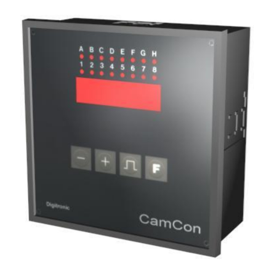
Digitronic Digital Cam Switch Unit Automationsanlagen GmbH CamCon DC33 5. Outline of the operator terminal 5.1. Frontview CamCon 5.2. The output display The output display shows the current states of the outputs. If a LED is illuminated, the corresponding output is active. -
Page 14: Commissioning
Digitronic Digital Cam Switch Unit Automationsanlagen GmbH CamCon DC33 6. Commissioning Before activating the device for the first time, please check its wiring (see chapter 4. Electrical connections). Attention: With induced loads the outputs have to be switched with a freewheeling diode. -
Page 15: The Encoder Resolution
Digitronic Digital Cam Switch Unit Automationsanlagen GmbH CamCon DC33 6.2.2. The encoder resolution The display shows the resolution of the encoder in steps per rotation. The CamCon operates with a standard encoder with a resolution of 360 steps per rotation. The resolution cannot be adjusted or changed. -
Page 16: Cam Programming In The Programming Mode "0
Digitronic Digital Cam Switch Unit Automationsanlagen GmbH CamCon DC33 6.4. Cam programming in the programming mode "0" 6.4.1. Selecting an output To initiate cam programming press the key for about 2 sec., until the display shows e.g. . This indicates that there is no programmed cam on output 1 in the 'Output selection' mode. -
Page 17: Leaving Cam Programming
Digitronic Digital Cam Switch Unit Automationsanlagen GmbH CamCon DC33 6.4.6. Leaving cam programming No matter in which programming mode you are, you can always leave cam programming by pressing key. The standard display appears 6.4.7. Examples for cam programming in the programming mode "0"... -
Page 18: Programming Additional Cams On An Output
Digitronic Digital Cam Switch Unit Automationsanlagen GmbH CamCon DC33 6.4.7.2. Programming additional cams on an output Task: A cam shall be programmed on output 2 from 300 to 330 in addition to an already existing cam, e.g. from 100 to 200. -
Page 19: Deletion Of A Particular Cam
Digitronic Digital Cam Switch Unit Automationsanlagen GmbH CamCon DC33 6.4.7.3. Deletion of a particular cam Task: The cam from 300 to 330 on output 2 shall be deleted. Solution: Press the key (for about 2 sec.), you enter the 'Output selection' mode... -
Page 20: Cam Programming In The Programming Mode "1
Digitronic Digital Cam Switch Unit Automationsanlagen GmbH CamCon DC33 6.5. Cam programming in the programming mode "1" 6.5.1. Selecting an output The cam programming is initiated as follows: Press the key for about 2 sec., until the display shows e.g. -
Page 21: Examples For Cam Programming In The Programming Mode "1
Digitronic Digital Cam Switch Unit Automationsanlagen GmbH CamCon DC33 6.5.5. Examples for cam programming in the programming mode "1" 6.5.5.1. Cam programming Task: After a complete deletion of the program memory and a successful initialization of the system, a cam shall be programmed on output 2 from 100 to 200. -
Page 22: Outline Of Operations
Digitronic Digital Cam Switch Unit Automationsanlagen GmbH CamCon DC33 7. Outline of operations 7.1. Switching the standard display Speed display (min -1 ) Press the key shortly Position display Speed display (min -1 ) Press the key shortly 7.2. Programming of the system constants... -
Page 23: Watch Doc
Digitronic Digital Cam Switch Unit Automationsanlagen GmbH CamCon DC33 8. watch doc The CamCon deactivates all output within 1ms when an error occurs. This behavior can be used as an extreme error message. Program a cam over the whole range of a chosen output (0 to 360 degrees) (security cam). -
Page 24: Technical Data Of The Camcon
Digitronic Digital Cam Switch Unit Automationsanlagen GmbH CamCon DC33 10. Technical data of the CamCon Multifunctional display for programming ..... 7-segment, 5-digits, 13mm Number of outputs ..........8 or 16 State display of the outputs......... a red LED each Number of programable cams ......500 Number of programs ........... -
Page 25: Key Word Table
Digitronic Digital Cam Switch Unit Automationsanlagen GmbH CamCon DC33 11. Key word table Activation point, Shifting........................16; 20 Cable covers ............................10 Cam programming ........................16; 20; 22 Cam programming, Examples ......................17; 21 CE ................................2 Commissioning ............................14 Connections, Electrical...........................
Need help?
Do you have a question about the CamCon DC33 and is the answer not in the manual?
Questions and answers