Table of Contents
Advertisement
Quick Links
DUAL DISPLAY MULTIMETER
THIS IS AN IEC SAFETY CLASS
FOR SAFETY.
Our company warrants to the original purchaser that each product it manufactures will be free from defects in
material and workmanship under normal use and service for a period of one year from date of purchase. Our
company's warranty does not apply to fuses, test leads or any product which, in our company's opinion, has been
misused, altered, or damaged by accident or abnormal conditions of operation or handling.
To obtain warranty service, contact the nearest Service Center or send the product, with a description of the difficulty,
and postage prepaid, to the nearest Service Center. We assume no risk for the damage in transit. We will, at its
option, repair or replace the defective product free of charge or refund your purchase price. However, if we determine
that the failure was caused by misuse, alterations, accident or abnormal condition of operation or handing, you will
be billed for the repair and the repaired product will be returned to you transportation prepaid.
All shipment of our company's instruments should be made via United Parcel Service or "Best Way" prepaid. The
instrument should be shipped in the original carton; or if it is not available, use any suitable container that is rigid and
of adequate size. If a substitute container is used, the instrument should be wrapped in paper and surrounded with at
least four inches of excelsior or similar shock-absorbing material.
The instrument should be thoroughly inspected immediately upon original delivery to purchaser. All material in the
container should be checked against the enclosed packing list. The manufacturer will not be responsible for
shortages against the packing sheet unless notified immediately. If the instrument is damaged in any way, a claim
should be filed with the carrier immediately. (To obtain a quotation to repair shipment damage, contact the nearest
Service Center.) Final claim and negotiations with the carrier must be completed by the customer.
1
PRODUCT. THE GROUND WIRE IN THE LINE CORD MUST BE CONNECTED
SHIPPING TO MANUFACTURER FOR REPAIR OR ADJUSTMENT
CLAIM FOR DAMAGE IN SHIPMENT TO ORIGINAL PURCHASER
CAUTION
WARRANTY
1
USER'S MANUAL
Advertisement
Table of Contents

Subscribe to Our Youtube Channel
Related Manuals for Victor 8145B


Summary of Contents for Victor 8145B
- Page 1 DUAL DISPLAY MULTIMETER USER’S MANUAL CAUTION THIS IS AN IEC SAFETY CLASS PRODUCT. THE GROUND WIRE IN THE LINE CORD MUST BE CONNECTED FOR SAFETY. WARRANTY Our company warrants to the original purchaser that each product it manufactures will be free from defects in material and workmanship under normal use and service for a period of one year from date of purchase.
- Page 2 Section 1 Introduction INTRODUCING THE DUAL DISPLAY MULTIMETER In this manual, “WARNING” is reserved for conditions and actions that pose hazard(s) to the user; “CAUTION” is reserved for conditions and actions that may damage your meter. NOTE This manual contains information and warnings that must be followed to ensure safe operation and retain the meter in safe condition.
-
Page 3: Getting Started
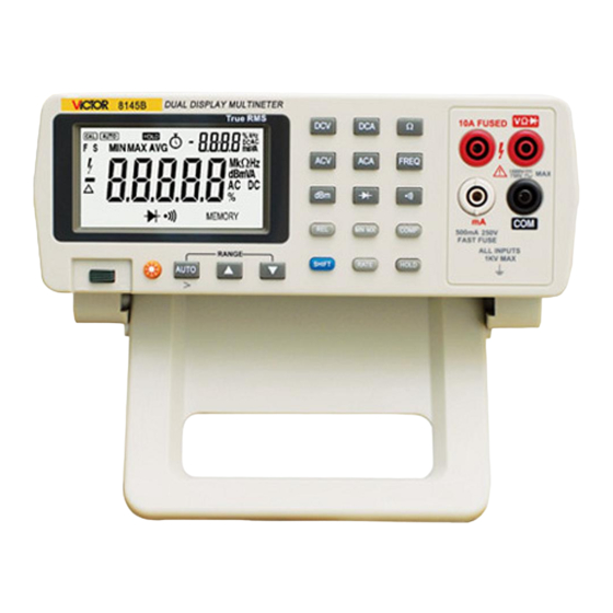
Front Panel and Rear Panel The front panel (shown in Figure 2-1) has three main elements: the input terminals on the right, the display and the pushbuttons. The pushbuttons are used to 8145B DUAL DISPLAY MULTIMETER 10A FUSED select major functions, ranging... -
Page 4: Adjusting The Handle
Figure 2-1. Front Panel The rear panel (shown in Figure 2-2) contains the power-line cord connector, communication interface, the Serial Number Label. TO AVOID SHOCK HAZARD, CONNECT THE INSTRUMENT POWER CORD TO A POWER RECEPTACLE WITH EARTH GROUND. THERE ARE NO PARTS TO DISASSEMBLE, NO MECHANICAL ADJUSTMENTS TO MAKE, 220V 50Hz... - Page 5 EXAMPLE: Press ACV to select volts ac function. Press a combination of buttons, one after the other. EXAMPLE: Press ACV to select volts ac function, and then press REL to select the decibels modifier. For more details on the uses of each button, refer to Section 3, “OPERATION THE METER FROM THE FRONT PANEL.”...
-
Page 6: Operating The Meter From The Front Panel
continuous beep when the input drops below 150Ω (Beep condition can be changed, refer to “Changing the Power-UP Configuration” later in Section 3), and the readings for the test circuit are displayed. The diode test measures the forward voltage of a semiconductor junction at approximately 0.8mA. Readings are displayed in the 3V range at the fast measurement rates. -
Page 7: Input Terminals
to desired range Turn on or turn off the back light (when arrive the setting time the back light can automatically off) Power-on or off the power supply (POWER) These operations are described in remainder of Section 3. DISPLAY The meter has a 5-digit, Liquid Crystal Display (Primary Display) and a 4-digit, Liquid Crystal Display (Secondary Display). - Page 8 A m p s D C R e s i s t a n c e V o l t s D C F r e q u e n c y D C V D C A A m p s A C A C V A C A F R E Q...
- Page 9 Manual Ranging Press AUTO to toggle in and out of manual ranging. The range you are in when you enter the manual range mode becomes the selected range. In manual range, the meter remains in the selected range regardless of input. Press AUTO to toggle back to autoranging.
- Page 10 For example, if the relative base is 15.000V, and the present reading is 14.100V, the display will show -6%. Press REL again to exit the relative modifier. NOTE The relative modifier cannot be selected if the display shows “OL” or is blank. (The display would be blank, for example, because of range changes.) Selecting the relative modifier (REL) turns off autoranging and locks in the present range.
-
Page 11: Selecting A Measurement Rate (Rate)
Selecting the Compare Modifier turns off autoranging and locks in the present range. Make sure you are in the correct range before selecting the Compare Modifier. The function modifier is relative to the measurement function refer to the Table 3-5 Table 3-5. -
Page 12: Maintenance
MIN/MAX/AVG Relative Base value Frequency of Power 50Hz Changeable Back Light Time 0000 S Changeable Continuity beep when the input drops below 150Ω Changeable Compare beep if the reading lower or higher set value Changeable Changing the Power-Up Configuration You can change the power-up configuration to one that more closely meet your needs and preferences. To change the Power-Up Configuration, power-up the meter and press SHIFT simultaneity Change Back Light Time: Press AUTO, when “bLOFF”... -
Page 13: Current Input Fuses
THE CASE. TO AVOID DAMAGING THE METER HOUSING, NEVER APPLY SOLVENTS TO THE METER. IF THE METER REQUIRES CLEANING, WIPE IT DOWN WITH A CLOTH THAT IS LIGHTLY DAMPENED WITH WATE OR A MILD DETERGENT. DO NOT USE AROMATIC HYDROCARBONS, CHLORINATED SOLVENTS, OR METHANOL-BASED FLUIDS WHEN WIPING DOWN THE METER. - Page 14 The following performance tests are provided to ensure that the meter is in proper operating condition. If the instrument fails any of the performance tests, then calibration adjustment and/or repair is needed. To perform these tests, you will need a 5520A Multifunction Calibrator or equivalents. Each of the measurements listed in the following steps assume the instrument is being tested after a one-hour warmup, in an environment with an ambient temperature of 18 to 28℃, and a relative humidity of less than70%.
- Page 15 REQUIRED EQUIPMENT (refer to the table5-1) Table5-1. Recommended Test Equipment Measurement Multifunction Range Accuracy±(%Output) Recommended Equipment 300mV,3V,30V,300V, 0.0002 1000V 20~50Hz 0.025 300mV,3V,30V,300V, 50 Hz~10KHz 0.015 1000V 10~20KHz 0.022 20~50KHz 0.03 300Ω,3KΩ,30KΩ, 300KΩ 0.004 OHMS FLUKE 3MΩ,30 MΩ,100 MΩ 0.05 0.3mA, 3mA, 30mA, 300mA 0.025 5520A 20~50Hz...
- Page 16 DC300mA 300.00 DC10A 3.0000 AC0.3mA(1KHz) 0.03000 0.30000 AC3mA(1KHz) 0.3000 3.0000 Current ac AC30mA(1KHz) 3.000 30.000 AC300mA(1KHz) 30.00 300.00 AC10A(1KHz) 0.300 3.000 Frequency(3V 3KHz 3.0000 of sine wave) NOTE To calibrator the meter, connect the instrument power cord to a power receptacle with earth ground. DC Volts calibration Turn on the meter, press the DCA, dBm and button simultaneity to enter calibration mode, and...
- Page 17 Connect the standard equipment with the meter as shown in Figure 5-3. 10A FUSED NORMAL SCOPE Press the button to select the 10A range. 1000V 750V Press the SHIFT button of the meter to calibrate TRIG the 10A range, and the display reads 3A, Applied 500mA 250V FAST FUSE...
- Page 18 Keep the meter at least 20 seconds, press the REL button to save the calibrated value, and the “SAVE” displayed on the LCD; if the “ERR” displayed, check the set value for the standard equipment, and inspect the function and the method of the line connection right or not newly. 10) Press the button change the range 11) Repeat step 3 to step 10 until complete all range.
-
Page 19: Specifications
Press the SHIFT button of the meter to calibrate the indicated range displayed on the meter. Keep the meter at least 10 seconds, press the REL button to save the calibrated value, and the “SAVE” displayed on the LCD; if the “ERR” displayed, check the set value for the standard equipment, and inspect the function and the method of the line connection right or not newly. - Page 20 Common Mode Rejection Ratio (CMR) ≥120dB (at 50Hz or 60Hz) Maximum Input 1000V peak TRUE RMS AC VOLTAGE, AC-COUPLED Accuracy Range Resolution 20~50Hz 50 Hz~10KHz 10~20KHz 20~30KHz 30~50KHz 300mV 10uV 1%+80 5%+80 10%+150 2%+30 100uV 0.5%+30 3%+30 300V 10mV 750V 100mV REMARK: Accuracy specifications apply to the range from 10% to 100% Input Impedance...
- Page 21 Maximum Crest Factor Range Resolution Accuracy Open Circuit Voltage Short Circuit Current 300Ω 10mΩ About 1mA 3KΩ 100 mΩ 0.05%+3 30 KΩ 1Ω About 250uA 300 KΩ 10Ω 2.5V About 25uA 3 MΩ 100Ω 0.1%+3 About 2.5uA 30MΩ 1 KΩ 0.2%+3 About 0.25uA 100MΩ...
- Page 22 ≤90% at 5℃ to 28℃ (non-condensing) Relative Humidity ≤80% at 28℃ to 40℃ ≤70% at 10℃ to 40℃ for the 300KΩ, 3MΩ and 30MΩ ranges. GENERAL 1000V dc or peak ac maximum from any input to earth Common Mode Voltage 245mm deep, 220mm wide, 82mm high Size about 2Kg...
Need help?
Do you have a question about the 8145B and is the answer not in the manual?
Questions and answers