Advertisement
Quick Links
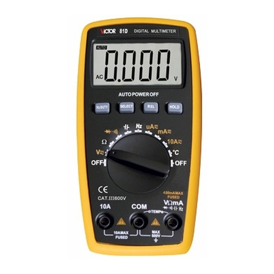
DIGITAL MULTIMETER
OPERATION MANUAL
I. General
This is equipped with the LCD display
of text height 18.9mm, is a 3 3/4 digital
multimeter which has the merits of clear
reading,
stable
reliability.
It could be used to measure DC voltage,
AC voltage, DC current, AC current,
resistance, temperature, capacity, frequency /
duty cycle, diode and make on-and-off test.
Meanwhile, it is available for unit symbol
display, automatic/manual range switching,
automatic power off and alarm function. The
complete machine takes an integrated circuit
which
can
microprocessor and double-integrating A/D
performance
directly
drive
and
high
LCD
8-bit
Advertisement

Related Manuals for Victor 81D


Summary of Contents for Victor 81D
- Page 1 DIGITAL MULTIMETER OPERATION MANUAL I. General This is equipped with the LCD display of text height 18.9mm, is a 3 3/4 digital multimeter which has the merits of clear reading, stable performance high reliability. It could be used to measure DC voltage, AC voltage, DC current, AC current, resistance, temperature, capacity, frequency / duty cycle, diode and make on-and-off test.
- Page 2 switching and a digital display drive offering high resolution and high precision. Due to its complete functions, high measurement accuracy and convenient operation, the multimeter is the ideal tool in laboratory and factory as well as for radio fans and family. Ⅱ.
- Page 3 Holster 1 PC III. Safety Considerations The design of meter is in accordance with IEC1010 clause (the safety standard issued International Electrotechnical Commission). Prior to the operation of the instrument, please first read the safety considerations. 1. When DC voltage above 30V, AC voltage above 25V, current above 10mA, AC power line with inductive load or power line during electric fluctuation is measured,...
- Page 4 grounded well and etc. in order to avoid electric shock. 3. Only if the meter is used with the matched meter pen, can it meet the requirement of safety standard. When the line of the meter pen is damaged, it is necessary to replace another one of the same model or the same electrical specification.
- Page 5 inside the meter. Only the battery of the same model same electrical specification can be replaced. Before the replacement, the test leads must leave the measuring point and ensure there is no any signal at the input terminal. 6. When the electrical measurement is made, never let your body gets in touch with the ground directly, and don’t touch uncovered metal terminal, output port, lead clamp and...
- Page 6 environment. 8. It may do damage to the meter and endanger the operator’s safety if the voltage value beyond permitted ultimate voltage value is measured. The ultimate voltage value permitted for measurement is marked on the instrument panel, and never measure the value exceeding the standard.
- Page 7 professional personnel who have had special training or gained approval can make it. 11. During measurement, the requirement of measurement function must accordance with LCD display. Please be sure to disconnect the line of the test leads with the measured object first and ensure there is no any input signal.
- Page 8 14. Please don’t change the circuits of the meter freely for fear that the meter be damaged and the safety be endangered. 15. Description of Safety Symbols IV. Instrument Panel& Button Function Description 1. Instrument Model Number 2.LCD Display: Display the measured data and unit.
- Page 9 button, the function could switch between DC/AC/ 3.2. RANGE(auto/manual range switch): it’s auto range switch after power-on, press this key switch to manual range. Under the manual range mode , Every pressing to this key will make the range get to upper one.press this key for more than 2 sec.
- Page 10 function.(Frequency/duty cycle):press this key to select frequency or duty cycle measurement mode. 4.Knob Switch:It could be used to change the measurement function and range. 5. Input Terminals 5.1.Current, Voltage, Diode, Resistance, Capacity, Frequency, Buzzer, Temperature“-”Input terminal. 5.2.10A“+”input terminal. 5.3.Voltage、Diode、Resistance, Capacity, Frequency, Buzzer, Temperature and “...
- Page 11 automatically shut down (enter sleeping mode) to save power if function buttons and knob switch are not operated in 15 minutes. In auto power off mode, press any function buttons or rotate the knob switch, the instrument will get into the auto power on mode (working mode);...
- Page 12 converter 1-4.Sampling Rage:Approx. 3 times / sec. 1-5.Over Range Indication:Display“OL” 1-6.Low Battery Indication: “ ”symbol appears; 1-7.Operation Environment: (0~40)℃, Relative Humidity: <80% ; 1-8 . Storage Environment: (0 ~ 50) ℃ , Relative Humidity: <80% ; 1-9.Power: 2pcs 1.5V batteries (“AAA”7# battery) 1-10.Dimension (size): 145×74×36mm 1-11.Weight: Approx.
- Page 13 2.Technical Property 2-1. Accuracy:±(a%×reading+digits),at (23±5)℃,relative humidity <75%. One year calibration guarantee since time dispatched from the factory. 2-2.Technic Specification 2-2-1. DCV 1. Turn the knob switch to " " Range; 2. The initiate state of the meter is in automatic range status, which shows "AUTO"...
- Page 14 Otherwise, there is a danger of meter being damaged. 2. When measuring high voltage, special attention should be given to personal safety and avoid your body getting in touch with high voltage circuit. Range Accuracy Resolution 400mV 100uV ±(0.5%+4d) 10mV 400V 100mV 600V...
- Page 15 2-2-2. ACV True RMS 1. Insert black test leads into the hole of “COM” and red one into " "; 2. Rotate function switch to " " gear, press “SELECT” button to select the AC measurement mode. 3. The initiate state of the meter is in automatic range status, which shows “AUTO"...
- Page 16 attention should be given to personal safety and avoid your body getting in touch with high voltage circuit. Range Accuracy Resolution ±(0.8%+6d) 10mV 400V 100mV 600V ±(1.0%+6d) Input Impedance: >10MΩ; Overload Protection: 600V DC or 600V AC Peak Value; Frequency Response: (50~200) Hz; Display: Average value response (RMS of sine wave).
- Page 17 input terminal. (Max 400mA), or 10A input terminal (Max 10A). 2. Rotate function switch to Current gear. The initiate state of the meter is in automatic range status, which shows "DC" symbol. Then connect the test leads to the tested circuit in serial, the tested current value and the current polarity of the point where the red one is contacted will be displayed...
- Page 18 Range Accuracy Resolution 400uA 0.1uA 4000uA ±(1.0%+10d) 40mA 10uA 400mA 100uA ±(1.2%+10d) 10mA Max measurement voltage drop: Full Range mA is 0.4V, A is 100mV; Max input current: 10A (less than 15 seconds); Overload Protection: 0.4A/250V restorable fuse, 10A/250V fuse. 2-2-4.
- Page 19 10A). 2. Rotate function switch to Current gear. Press “SELECT” button to select the AC measurement mode. Then connect the test leads to the tested circuit in serial, the tested current value and the current polarity of the point where the red one is contacted will be displayed on the screen simultaneously.
- Page 20 damage the meter. Range Accuracy Resolution 400uA 0.1uA 4000uA ±(1.5%+10d) 40mA 10uA 400mA 100uA ±(2.5%+15d) 10mA Max measurement voltage drop: Full Range mA is 0.4V, A is 100mV; Max input current: 10A (less than 15 seconds); Overload Protection: 0.4A/250V restorable fuse ,...
- Page 21 connect the test leads to the tested resistor. 3. When measuring the low resistance, please short-circuit the meter pens at first to test the wire resistance, and then deduct it from the actual resistance. Caution: 1. If “OL” is displayed on LCD, it indicates the tested resistance value has exceeded the present range limit, please select higher range to complete the measurement.
- Page 22 discharged completely. Accur Range Resolution 400Ω ±(0.8%+5d) 0.1Ω 4kΩ 1Ω 40kΩ 10Ω ±(0.8%+4d) 400kΩ 100Ω 4MΩ 1kΩ 40MΩ ±(1.2%+10d) 10kΩ Open Voltage circuit: Less than 200mV; Overload Protection: 250V DC or AC Peak Value; Note: When measuring at Range 400Ω, please short-circuit the meter pens at first to test the wire resistance, and then deduct it from the actual resistance.
- Page 23 2-2-6.Diode and Continuity Test 1. Insert the black meter pen to “COM” terminal and the red one to “ ” terminal. (The polarity of red test lead is “+”); 2. Rotate the Range to " " gear. Press “SELECT” button to select the Diode measurement mode;...
- Page 24 screen. 5. The complete diode testing includes forward and backward measurement, if the result does not meet the above; it means the diode is bad. 6. Press “SELECT” button to select the Continuity measurement mode. 7. Connect the meter pens to two points of the tested circuit.
- Page 25 Buzzer makes Open circuit a long sound voltage is Approx. if resistance is 0.5V less than 50Ω Overload Protection: 250V DC or AC Peak Value. CAUTION: DO NOT INPUT VOLTAGE AT THIS RANGE! 2-2-7. Capacity (C) 1. Rotate function switch to " "...
- Page 26 pressing "REL" button.) Caution: 1. Fully discharge the tested capacitor in case it damages the meter. 2. When measuring in-line capacitor, the power should be turned off and all capacitors should be discharged completely. 3. It takes about 30 seconds to input stable reading at 1000uF Range.
- Page 27 Overload Protection: 250V DC or AC Peak Value. 2-2-8. Frequency (F) 1. Connect test leads and shielded cable to “COM” 、 “ ” terminals. 2. Rotate function switch to “Hz” gear. Connect test leads and the cable to the signal source or the tested load. The tested signal will show on the screen.
- Page 28 mode when in the frequency range. 4. Don't input voltage of over 250V DC or AC peak value in case it damages the meter. Accur Range Resolution 0.001Hz 10Hz 0.01Hz 100Hz 0.1Hz 1kHz ±(0.5%+10) 10kHz 10Hz 100kHz 100Hz 1MHz 1kHz 30MHz 10kHz For your...
- Page 29 2-2-9. Temperature (℃/℉) 1. Rotate function switch to (℃/℉)gear. 2. Insert the cathode (black pin) of cold end (free end) of thermocouple into “COM” jack and anode into “ ” terminal. Then working (temperature measurement end) of thermocouple on the surface or inside the object to be tested.
- Page 30 Accura Range Resolution <400℃± (-20 ~ (1.0%+5d) 1℃ 1000)℃ ≥400℃± (1.5%+15d) <750℉± ~ (0.75%+5d) 1℉ 1832)℉ ≥750℉± (1.5%+15d) Sensor: Type Thermocouple (Nickel-chromium--nickel silicon) (banana plug). CAUTION: DO NOT INPUT VOLTAGE AT THIS RANGE! VII. Instrument Maintenance This is a precision instrument and the user - 30 -...
- Page 31 shall not modify the electric circuit at will. 1. Keep the instrument away from water, dust and shock. 2. Do not store and operate the meter under the condition of high temperature, high humidity, combustible, explosive and strong magnetic place. 3.
- Page 32 5-1. Loosen the screw on the back cover that secures the battery door and exit the battery door; 5-2. Remove the 1.5V batteries and replace them with two new ones. Although a 1.5V battery of any standard can be used, but in order to lengthen the operation life, alkaline batteries should be used.
- Page 33 back cover ahs not been tightened. 4. Prior to the replacement of battery or fuse, please remove the meter pens from the measuring point and switch off the meter. VIII. Fault Elimination If the instrument could not work properly, please try the following tips to solve some general problems.
- Page 34 This Instruction is subjected to change without any further notice. The content of this Instruction is considered correct, and in case readers find any errors and missing parts, please contact the manufacturer. The Company shall not be held liable for any accidents and hazards resulted from the mal-operations by the user.
Need help?
Do you have a question about the 81D and is the answer not in the manual?
Questions and answers