
Related Manuals for GORMAN-RUPP PUMPS 11 1/2A9-B


Summary of Contents for GORMAN-RUPP PUMPS 11 1/2A9-B
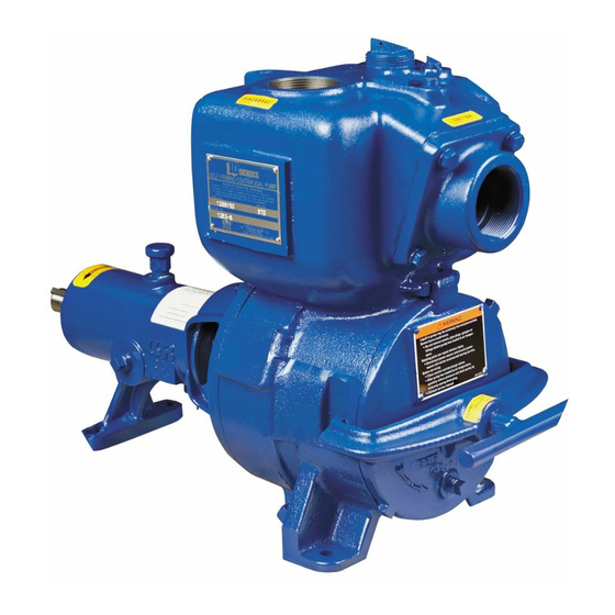
- Page 1 OM‐00570‐01 June 11, 1979 Rev. E 11‐22‐2016 INSTALLATION, OPERATION, AND MAINTENANCE MANUAL WITH PARTS LIST 10 SERIES PUMP MODEL 11 1/2A9‐B GORMAN‐RUPP PUMPS www.grpumps.com 1979 Gorman‐Rupp Pumps Printed in U.S.A.
- Page 2 Register your new Gorman‐Rupp pump online at www.grpumps.com Valid serial number and e‐mail address required. RECORD YOUR PUMP MODEL AND SERIAL NUMBER Please record your pump model and serial number in the spaces provided below. Your Gorman‐Rupp distributor needs this information when you require parts or service. Pump Model: Serial Number:...
-
Page 3: Table Of Contents
TABLE OF CONTENTS INTRODUCTION ..........PAGE I - 1 SAFETY ‐... - Page 4 TABLE OF CONTENTS (continued) TROUBLESHOOTING - SECTION D ......PAGE D - 1 PREVENTIVE MAINTENANCE .
-
Page 5: Introduction
10 SERIES OM-00570 INTRODUCTION Thank You for purchasing a Gorman‐Rupp pump. HAZARD AND INSTRUCTION Read this manual carefully to learn how to safely DEFINITIONS install and operate your pump. Failure to do so could result in personal injury or damage to the The following are used to alert maintenance per... -
Page 6: Safety - Section A
10 SERIES OM-00570 SAFETY ‐ SECTION A This information applies to 10 Series ba 6. Vent the pump slowly and cau sic pumps. Gorman‐Rupp has no con tiously. trol over or particular knowledge of the 7. Drain the pump. power source which will be used. Refer to the manual accompanying the power source before attempting to begin oper... - Page 7 OM-00570 10 SERIES Do not operate the pump without the Do not remove plates, covers, gauges, shields and/or guards in place over the pipe plugs, or fittings from an over drive shaft, belts, and/or couplings, or heated pump. Vapor pressure within the other rotating parts.
-
Page 8: Installation - Section B
See Figure 1 for the approximate physical dimen configuration, and priming must be tailored to the sions of this pump. OUTLINE DRAWING Figure 1. Pump Model 11 1/2A9-B INSTALLATION PAGE B - 1... -
Page 9: Preinstallation Inspection
OM-00570 10 SERIES PREINSTALLATION INSPECTION POSITIONING PUMP The pump assembly was inspected and tested be fore shipment from the factory. Before installation, inspect the pump for damage which may have oc Death or serious personal injury and curred during shipment. Check as follows: damage to the pump or components a. -
Page 10: Suction And Discharge Piping
10 SERIES OM-00570 Installation closer to the pump may result in erratic SUCTION AND DISCHARGE PIPING readings. SUCTION LINES Pump performance is adversely effected by in creased suction lift, discharge elevation, and fric To avoid air pockets which could affect pump prim tion losses. -
Page 11: Suction Lines In Sumps
OM-00570 10 SERIES Suction Lines In Sumps of one or both pumps. To avoid this, position the suction inlets so that they are separated by a dis If a single suction line is installed in a sump, it tance equal to at least 3 times the diameter of the should be positioned away from the wall of the suction pipe. -
Page 12: Discharge Lines
10 SERIES OM-00570 pass line should be at least 1 inch (25,4 mm) in di DISCHARGE LINES ameter to minimize the chance of plugging. Siphoning In low discharge head applications (less than 30 Do not terminate the discharge line at a level lower feet (9,1 m)), it is recommended that the bypass than that of the liquid being pumped unless a si... -
Page 13: Automatic Air Release Valve
OM-00570 10 SERIES stalled anywhere in a bypass line, it must moving the plug to prevent injury to per be a full‐opening, ball‐type valve to pre sonnel from hot liquid. vent plugging by solids. AUTOMATIC AIR RELEASE VALVE When properly installed, a Gorman‐Rupp Auto matic Air Release Valve will permit air to escape through the bypass line and then close automati... -
Page 14: Alignment
10 SERIES OM-00570 DISCHARGE PIPE CLEAN‐OUT COVER INSTALL AIR RELEASE VALVE IN HORIZONTAL POSITION DISCHARGE CHECK VALVE 90_ LONG RADIUS ELBOW SUPPORT PUMP DISCHARGE BRACKET SELF‐PRIMING CENTRIFUGAL PUMP BLEED LINE 1” (25,4 MM) DIA. MIN. (CUSTOMER FUR NISHED) DO NOT EX SUCTION TEND BELOW PUMP LINE... -
Page 15: Coupled Drives
OM-00570 10 SERIES when the hubs are the same distance apart at all points (see Figure 4B). Check parallel adjustment by laying a straightedge Adjusting the alignment in one direction across both coupling rims at the top, bottom, and may alter the alignment in another direc side. -
Page 16: V-Belt Tensioning
10 SERIES OM-00570 The ratio of deflection to belt span is 1:64 for both parts can catch clothing, fingers, or tools, causing severe injury to person ASA and metric units. Therefore, a belt with a span nel. of 64 inches would require a deflection of 1 inch at the force shown on the Tables for your particular V‐BELT TENSIONING application. - Page 17 OM-00570 10 SERIES Table 1. Sheave Diameter (Inches) Table 2. Sheave Diameter (Millimeters) Deflection Force (Lbs.) Deflection Force (KG.) Belt Deflection Force Belt Deflection Force Uncogged Cogged Uncogged Cogged Hy‐T Belts & Torque‐Flex Hy‐T Belts & Torque‐Flex Uncogged & Machined Uncogged &...
-
Page 18: Operation - Section C
OM-00570 10 SERIES OPERATION - SECTION C Review all SAFETY information in Section A. 1. The pump is being put into service for the first time. Follow the instructions on all tags, labels and 2. The pump has not been used for a consider decals attached to the pump. -
Page 19: Operation
OM-00570 10 SERIES Consult the operating manual furnished with the filled, adjust the throttling valve to the required flow power source before attempting to start the power rate. source. Leakage If an electric motor is used to drive the pump, re move V‐belts, couplings, or otherwise disconnect No leakage should be visible at pump mating sur... -
Page 20: Pump Vacuum Check
OM-00570 10 SERIES maximum permissible operating pressure shown BEARING TEMPERATURE CHECK on the pump performance curve (see Section E, Page 1). Bearings normally run at higher than ambient tem peratures because of heat generated by friction. Temperatures up to 160_F (71_C) are considered Pump Vacuum Check normal for bearings, and they can operate safely to at least 180_F (82_C). - Page 21 10 SERIES OM-00570 TROUBLESHOOTING - SECTION D Review all SAFETY information in Section A. Before attempting to open or service the pump: 1. Familiarize yourself with this manual. 2. Disconnect or lock out the power source to ensure that the pump will remain inoperative.
- Page 22 OM-00570 10 SERIES TROUBLE POSSIBLE CAUSE PROBABLE REMEDY Impeller or other wearing parts worn Replace worn or damaged parts. PUMP STOPS OR FAILS TO DELIVER or damaged. Check that impeller is properly RATED FLOW OR centered and rotates freely. PRESSURE (cont.) Impeller clogged.
- Page 23 10 SERIES OM-00570 equipped) between regularly scheduled inspec PREVENTIVE MAINTENANCE tions can indicate problems that can be corrected Since pump applications are seldom identical, and before system damage or catastrophic failure oc pump wear is directly affected by such things as curs.
- Page 24 PUMP MAINTENANCE AND REPAIR ‐ SECTION E MAINTENANCE AND REPAIR OF THE WEARING PARTS OF THE PUMP WILL MAINTAIN PEAK OPERATING PERFORMANCE. STANDARD PERFORMANCE FOR PUMP MODEL 11 1/2A9-B Based on 70_F (21_C) clear water at sea level Contact the Gorman‐Rupp Company to verify per...
- Page 25 OM-00570 10 SERIES PARTS PAGE SECTION DRAWING Figure E-1. Pump Model 11 1/2A9-B PAGE E - 2 MAINTENANCE & REPAIR...
- Page 26 10 SERIES OM-00570 PARTS LIST Pump Model 11 1/2A9-B (From S/N 376069 Up) If your pump serial number is followed by an “N”, your pump is NOT a standard production model. Contact the Gorman‐Rupp Company to verify part numbers. ITEM...
- Page 27 OM-00570 10 SERIES PUMP AND SEAL DISASSEMBLY 3. Allow the pump to completely cool AND REASSEMBLY if overheated. 4. Check the temperature before opening any covers, plates, or Review all SAFETY information in Section A. plugs. 5. Close the suction and discharge Follow the instructions on all tags, label and de...
- Page 28 10 SERIES OM-00570 Pump Casing Removal (when facing the drive end of the shaft). The impel ler may also be loosened by using a long piece of heavy bar stock to pry against the arm of the lathe dog in a counterclockwise direction (when facing the drive end of the shaft) as shown in Figure 2.
- Page 29 OM-00570 10 SERIES the seal plate. Remove the stationary portion of the the shaft, it is recommended that bearings seal from the seal clamp. be cleaned and inspected in place. It is strongly recommended that the bearings If no further disassembly is required, see Seal be replaced any time the shaft and bear...
- Page 30 10 SERIES OM-00570 Shaft and Bearing Reassembly out of position in shrinking. If movement has oc and Installation curred, use a suitably sized sleeve and a press to reposition the bearings. Clean and inspect the bearings as indicated in If heating the bearings is not practical, use a suit Shaft and Bearing Removal and Disassembly.
- Page 31 OM-00570 10 SERIES Seal Reassembly and Installation Handle the seal parts with extreme care to prevent damage. Be careful not to contaminate precision Clean the seal cavity and shaft with a cloth soaked finished faces; even fingerprints on the faces can in fresh cleaning solvent.
- Page 32 10 SERIES OM-00570 SEALING DISC SEAL CLAMP WEDGE SPRING IMPELLER GASKETS IMPELLER SHAFT SHAFT SLEEVE STATIONARY SEAT IMPELLER SHIMS ROTATING RETAINER ELEMENT SEAL PLATE Figure 3. Seal Assembly Slide the rotating portion of the seal onto the lubri cated shaft sleeve to the dimension (or scribed line) noted during disassembly.
- Page 33 OM-00570 10 SERIES Pump Casing Installation Secure the back cover assembly by installing the clamp bar (42) and tightening the clamp bar screw Remove the hardware temporarily securing the (44). Do not over‐tighten the clamp bar screw; it seal plate to the pedestal. Install the same thick should be just tight enough to seal the back cover ness of pump casing gaskets (35) as previously re...
- Page 34 10 SERIES OM-00570 Under normal conditions, change the grease after LUBRICATION each 5000 hours of operation, or at 12 month inter vals, whichever comes first. Change the grease Bearings more frequently if the pump is operated continu ously or installed in an environment where variable The pedestal was fully lubricated when shipped hot and cold temperatures are common.
- Page 35 For Warranty Information, Please Visit www.grpumps.com/warranty or call: U.S.: 419-755-1280 Canada: 519-631-2870 International: +1-419-755-1352 GORMAN‐RUPP PUMPS...
Need help?
Do you have a question about the 11 1/2A9-B and is the answer not in the manual?
Questions and answers