Advertisement
Quick Links
USER GUIDE & SERVICE MANUAL
SAFETY • INSTALLATION & INTEGRATION • OPERATING INSTRUCTIONS • MAINTENANCE • SERVICE
RIGHT PRODUCT. RIGHT PLACE. RIGHT TEMPERATURE. SINCE 1962.
Modular 3000 Series
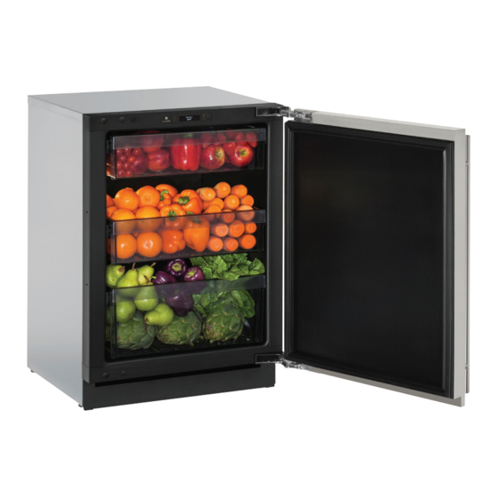
3024R
24" Solid Door Refrigerator
•
•
SAFETY • INSTALLATION & INTEGRATION • OPERATING INSTRUCTIONS • MAINTENANCE • SERVICE
Contents
Safety
Safety and Warning
Intro
Advertisement

Related Manuals for U-Line U-3024RS-00B


Summary of Contents for U-Line U-3024RS-00B
- Page 1 USER GUIDE & SERVICE MANUAL SAFETY • INSTALLATION & INTEGRATION • OPERATING INSTRUCTIONS • MAINTENANCE • SERVICE RIGHT PRODUCT. RIGHT PLACE. RIGHT TEMPERATURE. SINCE 1962. Modular 3000 Series 3024R 24" Solid Door Refrigerator • • SAFETY • INSTALLATION & INTEGRATION • OPERATING INSTRUCTIONS • MAINTENANCE • SERVICE Contents Safety Safety and Warning...
- Page 2 Extended Non-Use WELCOME TO U-LINE Congratulations on your U-Line purchase. Your product comes from a company with over five decades of premium modular ice making, refrigeration, and wine preservation experience. U-Line continues to be the American leader, delivering versatility and flexibility for multiple applications including residential, light commercial, outdoor and marine use.
- Page 3 1. U-Line Customer Care must be contacted immediately at +1.800.779.2547. 2. Service or repairs performed on the unit without prior written approval from U-Line is not permitted. If the unit has been altered or repaired in the field without prior written approval from U-Line, claims will not be eligible.
- Page 4 USER GUIDE SAFETY • INSTALLATION & INTEGRATION • OPERATING INSTRUCTIONS • MAINTENANCE • SERVICE Safety and Warning WARNING Service must be done by factory authorized NOTICE service personnel. Any parts shall be replaced Please read all instructions before installing, with like components.
- Page 5 USER GUIDE u-line.com Disposal and Recycling DANGER RISK OF CHILD ENTRAPMENT. Before you throw away your old refrigerator or freezer, take off the doors and leave shelves in place so children may not easily climb inside. If the unit is being removed from service for disposal,...
- Page 6 USER GUIDE u-line.com SAFETY • INSTALLATION & INTEGRATION • OPERATING INSTRUCTIONS • MAINTENANCE • SERVICE Environmental Requirements This model is intended for indoor/interior applications only and is not to be used in installations that are open/ exposed to natural elements.
- Page 7 USER GUIDE u-line.com SAFETY • INSTALLATION & INTEGRATION • OPERATING INSTRUCTIONS • MAINTENANCE • SERVICE Electrical WARNING SHOCK HAZARD — Electrical Grounding Required. Never attempt to repair or perform maintenance on the unit until the electricity has been disconnected. Never remove the round grounding prong from the plug and never use a two-prong grounding adapter.
- Page 8 Cutout Dimensions Metric measurements rounded and optimized PREPARE SITE Your U-Line product has been designed exclusively for a built-in installation. When built-in, your unit does not require additional air space for top, sides, or rear. However, the front grille must NOT be obstructed.
- Page 9 USER GUIDE u-line.com SAFETY • INSTALLATION & INTEGRATION • OPERATING INSTRUCTIONS • MAINTENANCE • SERVICE Product Dimensions...
- Page 10 USER GUIDE u-line.com SAFETY • INSTALLATION & INTEGRATION • OPERATING INSTRUCTIONS • MAINTENANCE • SERVICE Product Dimensions 1 Side-by-Side Installation Hinge-by-Hinge Installation (Mullion) When installing two units hinge-by-hinge, 13/16" (22 OTHER SITE REQUIREMENTS mm) is required for integrated models. Additional...
- Page 11 USER GUIDE u-line.com SAFETY • INSTALLATION & INTEGRATION • OPERATING INSTRUCTIONS • MAINTENANCE • SERVICE Side-by-Side Installation 1 Anti-Tip Bracket CAUTION The anti-tip bracket must be installed to prevent the unit from tipping when doors are fully opened or excess weight is placed on the front of the unit.
- Page 12 USER GUIDE u-line.com SAFETY • INSTALLATION & INTEGRATION • OPERATING INSTRUCTIONS • MAINTENANCE • SERVICE Anti-Tip Bracket 1 2. Gently push the unit into position. Be careful not General Installation to entangle the cord. LEVELING INFORMATION 3. Re-check the leveling, from front to back and side 1.
- Page 13 3. Apply double sided tape to the backside of the integrated grill (plinth strip/base fascia). Use the diagram below for reference. U-Line recommends ™ ™ tape, a high strength bonding tape. Apply Tape To Shaded Area 4.
- Page 14 USER GUIDE u-line.com SAFETY • INSTALLATION & INTEGRATION • OPERATING INSTRUCTIONS • MAINTENANCE • SERVICE Grille - Plinth Installation (plinth strip/base fascia) 1. Align slots in grille (plinth strip/base fascia) rail REMOVING AND INSTALLING GRILLE with screw heads in base of unit...
- Page 15 90° open and try Door Stop again. Your U-Line unit was shipped to you with the optional 90° pin. Your unit’s door(s) will open 115° straight from the factory. If you would like the door stop at 90° follow these instructions.
- Page 16 USER GUIDE u-line.com SAFETY • INSTALLATION & INTEGRATION • OPERATING INSTRUCTIONS • MAINTENANCE • SERVICE Door Adjustments DOOR ALIGNMENT AND ADJUSTMENT Align and adjust the door if it is not level or is not sealing properly. If the door is not sealed, the unit may not cool properly, or excessive frost or condensation may form in the interior.
- Page 17 USER GUIDE u-line.com SAFETY • INSTALLATION & INTEGRATION • OPERATING INSTRUCTIONS • MAINTENANCE • SERVICE Door Adjustments 1...
- Page 18 USER GUIDE u-line.com SAFETY • INSTALLATION & INTEGRATION • OPERATING INSTRUCTIONS • MAINTENANCE • SERVICE 3. Using T-25 Torx bit loosen screw #1 and remove screw #2 on top and bottom hinge. Slide and remove the door from unit. Completely remove screw #1 on top and bottom.
- Page 19 USER GUIDE u-line.com SAFETY • INSTALLATION & INTEGRATION • OPERATING INSTRUCTIONS • MAINTENANCE • SERVICE Door Adjustments 2...
- Page 20 SAFETY • INSTALLATION & INTEGRATION • OPERATING INSTRUCTIONS • MAINTENANCE • SERVICE First Use All U-Line controls are preset at the factory. Initial startup requires no adjustments. NOTICE U-Line recommends allowing the unit to run overnight before loading with product.
- Page 21 USER GUIDE u-line.com SAFETY • INSTALLATION & INTEGRATION • OPERATING INSTRUCTIONS • MAINTENANCE • SERVICE First Use 1 Control Operation Zone Toggle Select Root 5 O°F Can be displayed in Celsius Power Down U-Select Lighting CONTROL FUNCTION GUIDE FUNCTION COMMAND DISPLAY/OPTIONS Display will count down from 5 to off.
- Page 22 Food Types Deli Meats, Fish, Cheeses, Dairy, Butter, Garlic, Interior Lighting Oils, Nuts, Condiments Your U-Line 3000 Series unit uses a state of the art Market/Fresh Fruits, Vegetables, Berries, Lettuce LED lighting system. The 3036 model dual zone’s Pantry Dry Goods, Breads, Baking Items, Spices,...
- Page 23 Customer Care if Hours”, “On 6 Hours”, or “On 24 Hours”. minutes. persistent. CUSTOMER MENU The 3000 Series of U-Line undercounter refrigeration 4. To exit, press or simply wait for the menu to appliances contains a feature rich customer menu. time out.
- Page 24 Customer Menu, select Energy Saver and change “On” to “Off”. 3. To return to the Customer Menu, press Languages Energy Saver Mode The U-Line 3000 Series of models supports a number of display languages including English, Spanish, Energy Saver Mode...
- Page 25 USER GUIDE u-line.com SAFETY • INSTALLATION & INTEGRATION • OPERATING INSTRUCTIONS • MAINTENANCE • SERVICE 4. Press to cycle through the available languages. To change from Fahrenheit to Celsius enter the Fahrenheit / Celsius Menu from within the Customer Menu.
- Page 26 To access the Help Menu, select “Help” from the Customer Menu. Press to scroll through available information. The Help screen displays the following: • Model. • U-Line contact information. • Software version. • Serial Number. To exit the Help menu, press to select “Return to Menu” and press to confirm.
- Page 27 USER GUIDE u-line.com SAFETY • INSTALLATION & INTEGRATION • OPERATING INSTRUCTIONS • MAINTENANCE • SERVICE The Display will fade out as the unit enters Sabbath Mode. Sabbath Mode remains active until is quickly pressed and Sabbath Mode released. Select RETURN TO MENU...
- Page 28 Do not install the unit behind a door. When properly loaded, your U-Line unit will store up to 141 (12 oz. [330 ml]) cans or 100 (12 oz. [330 ml]) bottles.
- Page 29 USER GUIDE u-line.com RATION • Airflow and Product Loading 1 OPERATING INSTRUCTIONS • MAINTENANCE • SERVICE Refrigerator Bins - Crisper may be used if necessary. Be sure to completely dry your bin before reinstalling. REFRIGERATOR BIN INSTALLATION & REMOVAL Refrigerator bins are easily removed for cleaning and NOTICE sanitizing.
- Page 30 USER GUIDE u-line.com SAFETY • INSTALLATION & INTEGRATION • OPERATING INSTRUCTIONS • • SERVICE MAINTENANCE Cleaning Integrated Models To clean integrated panels, use household cleaner per EXTERIOR CLEANING the cabinet manufacturer’s recommendation. Stainless Models Stainless door panels and handles can discolor when...
- Page 31 USER GUIDE u-line.com Cleaning 1 SAFETY • INSTALLATION & INTEGRATION • OPERATING INSTRUCTIONS • • SERVICE MAINTENANCE NOTICE The drain pan was not designed to capture the water created when manually defrosting. To prevent water from overflowing the drain pan and possibly damaging water sensitive flooring, the unit must be removed from cabinetry.
- Page 32 USER GUIDE u-line.com Cleaning 2 SAFETY • INSTALLATION & INTEGRATION • OPERATING INSTRUCTIONS • MAINTENANCE • SERVICE Cleaning Condenser INTERVAL - EVERY SIX MONTHS To maintain operational efficiency, keep the front grille (plinth strip/base fascia) free of dust and lint, and clean the condenser when necessary.
- Page 33 If the unit will be exposed to temperatures of 40°F (5°C) or less, the steps above must be followed. For questions regarding winterization, please call U-Line at +1.800.779.2547. CAUTION Damage caused by freezing temperatures is not covered by the warranty.
- Page 34 USER GUIDE u-line.com Extended Non-Use 1...
- Page 35 • Compressor: The compressor makes a hum or pulsing sound that may be heard when it operates. BEFORE CALLING FOR SERVICE If you think your U-Line product is malfunctioning, • Evaporator: Refrigerant flowing through an read the CONTROL OPERATION section to clearly evaporator may sound like boiling liquid.
- Page 36 (L) (R) Temp Left or right zone Verify door is closed properly. For other error codes contact temperature +10° and sealing. Contact U-Line Customer Service. 12H+ over set point for Customer Care if Because product in contact with the rear Product Is over 12 hours.
- Page 37 USER GUIDE u-line.com SAFETY • INSTALLATION & INTEGRATION • OPERATING INSTRUCTIONS • MAINTENANCE • SERVICE 4. Place the bottle in the desired area for 24 hours. 5. Avoid opening the unit during the testing period. 6. After 24 hours, check the temperature of the water.
- Page 38 • Food, beverage, and medicine loss are not covered by these warranties. • If the product is located in an area where U-Line factory authorized service is not available, you may be responsible for a trip charge or you may be required to bring the product to a U-Line factory authorized service location at your own cost and expense.
- Page 39 USER GUIDE u-line.com SAFETY • INSTALLATION & INTEGRATION • OPERATING INSTRUCTIONS • MAINTENANCE • SERVICE Copyright © 2014/2017 U-Line Corporation. All Rights Reserved. | Publication Number 30379 | 04/2017 Rev. K Warranty 1 Wire Diagram...
- Page 40 The part that caused the damage must be returned to U-Line in its entirety. The part must be clearly labeled with the serial number of the unit it was removed from, the date, and the servicer who removed the part.
- Page 41 USER GUIDE u-line.com SAFETY • INSTALLATION & INTEGRATION • OPERATING INSTRUCTIONS • MAINTENANCE • SERVICE Product Liability 1 Warranty Claims • Alternatively, a Proof of Purchase (or equivalent) may submitted with the warranty claim to The following information defines the parameters for...
- Page 42 USER GUIDE u-line.com SAFETY • INSTALLATION & INTEGRATION • OPERATING INSTRUCTIONS • MAINTENANCE • SERVICE Warranty Claims 1...
- Page 44 Some parts will require color or voltage information. If U-Line requires the return of original parts, we will inform you when the parts order is taken. This requirement will be noted on your packing list. A prepaid shipping label will be included with the replacement part.
- Page 45 USER GUIDE u-line.com SAFETY • INSTALLATION & INTEGRATION • OPERATING INSTRUCTIONS • MAINTENANCE • SERVICE Ordering Replacement Parts 1 USER GUIDE System Diagnosis Guide REFRIGERATION SYSTEM DIAGNOSIS GUIDE System Suction Suction Compressor Condenser Capillary Evaporator Wattage Condition Pressure Line Discharge...
- Page 46 SAFETY • INSTALLATION & INTEGRATION • OPERATING INSTRUCTIONS • MAINTENANCE • SERVICE To ensure the windings are not shorted, check the S Compressor Specifications 1 and R to ground. EMX20CLC Refrigerant R600a Voltage 115 - 127 VAC Frequency 60 Hz Run Cap 12μF/165 VAC...
- Page 47 USER GUIDE u-line.com SAFETY • INSTALLATION & INTEGRATION • OPERATING INSTRUCTIONS • MAINTENANCE • SERVICE Troubleshooting - Extended SPECIFIC ERRORS AND ISSUES The technically advanced diagnostic capabilities of the electronic controls utilized on the 3000 series units allows for easy and thorough trouble shooting.
- Page 48 USER GUIDE u-line.com SAFETY • INSTALLATION & INTEGRATION • OPERATING INSTRUCTIONS • MAINTENANCE • SERVICE electrical power has been disconnected from the unit. TROUBLESHOOTING GUIDE Concern Potential Causes Suggested Remedy Not Cooling Compressor overheating Verify proper air flow through condenser (Refer to Airflow/General Information Section).
- Page 49 USER GUIDE u-line.com SAFETY • INSTALLATION & INTEGRATION • OPERATING INSTRUCTIONS • MAINTENANCE • SERVICE Fan blade obstruction (wiring, foam Remove obstruction. insulation, packaging material) MAIN CONTROL The main control board is very robust and is rarely the cause of system issues. It is important to fully...
- Page 50 USER GUIDE u-line.com SAFETY • INSTALLATION & INTEGRATION • OPERATING INSTRUCTIONS • MAINTENANCE • SERVICE Relay & DC Outputs proper safety procedures while performing tests on live systems. One of the primary functions of the main control is to operate the multiple relay and DC outputs during each cycle.
- Page 51 USER GUIDE u-line.com SAFETY • INSTALLATION & INTEGRATION • OPERATING INSTRUCTIONS • MAINTENANCE • SERVICE FAULT SYSTEM DIAGNOSIS GUIDE Error Solution 1 Solution 2 Solution 3 No Comm Inspect Customer UI and Data Cable (if defective replace entire door) Zone T Open...
- Page 52 USER GUIDE u-line.com SAFETY • INSTALLATION & INTEGRATION • OPERATING INSTRUCTIONS • MAINTENANCE • SERVICE Market/Fresh 10 min. 45 min. Root 5 min. 90 min. Pantry 10 min. 45 min. Deli 10 min. 45 min. Zone Thermistor If the zone thermistor fails, the unit will continue to operate in a timed limp mode which varies by model.
- Page 53 USER GUIDE u-line.com SAFETY • INSTALLATION & INTEGRATION • OPERATING INSTRUCTIONS • MAINTENANCE • SERVICE Control Operation - Service SHOWS TEMPERATURES WITHOUT OFFSETS. EACH ZONE HAS AN RETURN TO MENU ACTUAL TEMPS ACTUAL TEMPS EVAP AND AIR THERMISTOR. EACH UNIT HAS AN AMBIENT THERMISTOR LEFT ZONE = 52°...
- Page 54 USER GUIDE u-line.com SAFETY • INSTALLATION & INTEGRATION • OPERATING INSTRUCTIONS • MAINTENANCE • SERVICE SERVICE MENU currently active. The error log memory is non volatile and is persistent should power be lost and restored to In addition to a feature rich customer menu, the 3000 the unit.
- Page 55 USER GUIDE u-line.com SAFETY • INSTALLATION & INTEGRATION • OPERATING INSTRUCTIONS • MAINTENANCE • SERVICE IDDescriptionSolution 1. Press to select “All Errors”. Ambient Check thermistor connection Thrm thermistor circuit harness for moisture 2. Press Shortshorted.corrosion. Also check connection where thermistor harness 3.
- Page 56 USER GUIDE u-line.com SAFETY • INSTALLATION & INTEGRATION • OPERATING INSTRUCTIONS • MAINTENANCE • SERVICE To access Relay Status 6. Press to scroll through each relay and DC output. 1. Use to select “Relay Status”. 7. Press to toggle. To exit the Relay Toggle menu press to select 2.
- Page 57 USER GUIDE u-line.com SAFETY • INSTALLATION & INTEGRATION • OPERATING INSTRUCTIONS • MAINTENANCE • SERVICE 3. Press to scroll through available Evap Fan Evaporator Fan 0 or 100% thermistors. Condenser Condenser Fan 0 or 100% Light Zone Lighting Off - Low - Med - High...
- Page 58 USER GUIDE u-line.com SAFETY • INSTALLATION & INTEGRATION • OPERATING INSTRUCTIONS • MAINTENANCE • SERVICE Differentials The Evap Fan option in the service menu allows servicers to change the Evaporator Fan runtime (in Select minutes) from 0 to 98 and OFF cycle time 0 to 98.
- Page 59 Down Press to select “Factory Wi- NOTICE Fi”. Before altering model selection U-Line customer service must be notified. Failure to notify customer service will result in voiding of the Press manufacturer warranty. Re-Select Model allows the units model information to 3.
- Page 60 USER GUIDE u-line.com SAFETY • INSTALLATION & INTEGRATION • OPERATING INSTRUCTIONS • MAINTENANCE • SERVICE Fan Delay To exit the Factory Wi-Fi menu press to select “Return to Menu” and press to confirm outputs. Select RETURN TO MENU FAN DELAY...
- Page 61 USER GUIDE u-line.com SAFETY • INSTALLATION & INTEGRATION • OPERATING INSTRUCTIONS • MAINTENANCE • SERVICE Showroom Mode Select RETURN TO MENU SHOWROOM MODE Down Showroom displays a number of features and allows the unit to be powered on without running the cooling system.
- Page 62 USER GUIDE u-line.com SAFETY • INSTALLATION & INTEGRATION • OPERATING INSTRUCTIONS • MAINTENANCE • SERVICE Thermistors Thermistor three (Ambient): Located in the base of the unit (secured to the Thermistors are used for various temperature condenser). It is used to monitor the ambient readings.
- Page 63 USER GUIDE u-line.com SAFETY • INSTALLATION & INTEGRATION • OPERATING INSTRUCTIONS • MAINTENANCE • SERVICE If the thermistor fails the unit will operate normally. Thermistor 1 Thermistor Resistance Data Nominal Resistance Temp (F) Temp (C) (OHMS)* 169157 121795 88766 65333...
- Page 64 USER GUIDE u-line.com SAFETY • INSTALLATION & INTEGRATION • OPERATING INSTRUCTIONS • MAINTENANCE • SERVICE Thermistor 2 Defrost The models below have automatic or frost free design and do not require manual defrosting under normal conditions. Defrost Settings Base Model...
- Page 65 USER GUIDE u-line.com SAFETY • INSTALLATION & INTEGRATION • OPERATING INSTRUCTIONS • MAINTENANCE • SERVICE or if not currently cooling, the fan will run for 1 8. Remove rear shelf clips, fronts can remain. minute to circulate air and clear any condensation that may have appeared on glass doors and shelves.
- Page 66 USER GUIDE u-line.com SAFETY • INSTALLATION & INTEGRATION • OPERATING INSTRUCTIONS • MAINTENANCE • SERVICE 14.Remove and replace fan. Take special care to properly route fan wire. NOTICE Fan must be oriented to pull air in through lower evaporator cover vents and push air out at fan mounting location.
Need help?
Do you have a question about the U-3024RS-00B and is the answer not in the manual?
Questions and answers