U-Line Modular 3000 Series User Manual & Service Manual
Hide thumbs
Also See for Modular 3000 Series:
- User manual & service manual (80 pages) ,
- Quick start manual (14 pages) ,
- User manual (12 pages)

Related Manuals for U-Line Modular 3000 Series


Summary of Contents for U-Line Modular 3000 Series
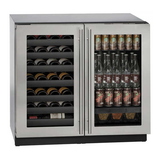
- Page 1 USER GUIDE & SERVICE MANUAL SAFETY • INSTALLATION & INTEGRATION • OPERATING INSTRUCTIONS • MAINTENANCE • SERVICE RIGHT PRODUCT. RIGHT PLACE. RIGHT TEMPERATURE. SINCE 1962. Modular 3000 Series 3036BVWC 36" Beverage Center • •...
- Page 2 USER GUIDE & SERVICE MANUAL u-line.com Table of Contents Installation Integrated Panel Dimensions Integrated Panel Installation Integrated Grille Dimensions Grille / Plinth Installation...
- Page 3 ® to preserve the right product, in the right place, at the right temperature. Since 2014, U-Line has been part of the Middleby family of brands. All products are designed, engineered, and assembled in Milwaukee, Wisconsin, USA, and select products are available worldwide.
- Page 4 USER GUIDE u-line.com SAFETY • INSTALLATION & INTEGRATION • OPERATING INSTRUCTIONS • MAINTENANCE • SERVICE Integrated Panel Dimensions Integrated Frame Dimensions Metric measurements rounded and optimized. BACK SURFACE MUST HAVE AMPLE FLAT SURFACE 3/4" TO MOUNT OVERLAY FRAME FLAT AND WITHOUT...
- Page 5 3-1/2" (89 mm) NOTE: Many cabinet manufacturers provide a ready solution for a handleless, integrated design that can be easily applied to your U-Line 3000 Series model. Consult Wooden Insert your cabinet manufacturer for applicable design and installation details. The cabinet manufacturer’s solution to...
- Page 6 USER GUIDE u-line.com SAFETY • INSTALLATION & INTEGRATION • OPERATING INSTRUCTIONS • MAINTENANCE • SERVICE Handleless Integrated Frame Dimensions 1/8" (3 mm) Top Design 1/4" (6 mm) 7/8" (22 mm) Ref. R 5/8" 2-3/8" (R 16 mm) (60 mm) 17-5/8”...
- Page 7 USER GUIDE u-line.com SAFETY • INSTALLATION & INTEGRATION • OPERATING INSTRUCTIONS • MAINTENANCE • SERVICE EXTENDED INTEGRATED FRAME NOTICE Due to differences in surrounding cabinetry the panel may not perfectly align with door. The procedure below is designed to provide a finished panel that seamlessly integrates with surrounding cabinetry.
- Page 8 USER GUIDE u-line.com SAFETY • INSTALLATION & INTEGRATION • OPERATING INSTRUCTIONS • MAINTENANCE • SERVICE Integrated Panel/Integrated Frame Integrated Panel U-Line U-Line Cabinet Unit Unit 3-5/16" (89 mm) 3-5/16" (89 mm) > 3-5/16" (> 89 mm) 4-5/16" (114 mm) 4-5/16" (114 mm)
- Page 9 USER GUIDE u-line.com SAFETY • INSTALLATION & INTEGRATION • OPERATING INSTRUCTIONS • MAINTENANCE • SERVICE Extended Integrated Frame Dimensions BACK SURFACE MUST HAVE AMPLE FLAT SURFACE 3/4" TO MOUNT INTEGRATED FRAME FLAT AND WITHOUT INTERFERENCE (20 mm) 17-5/8" (445 mm) 2-3/4"...
- Page 10 3. Apply double sided tape to the backside of the integrated grill (plinth strip/base fascia). Use the diagram below for reference. U-Line recommends ™ ™ tape, a high strength bonding tape.
- Page 11 Clamp clamps. A robust NOTICE tape may also be If panel requires additional adjustment after used. U-Line removing clamps, slightly loosen each screw and recommends the adjust panel as necessary. Tighten screws upon use of bar clamps Door/Drawer completion.
- Page 12 USER GUIDE u-line.com SAFETY • INSTALLATION & INTEGRATION • OPERATING INSTRUCTIONS • MAINTENANCE • SERVICE Grille - Plinth Installation Installing the grille (plinth strip/base fascia) REMOVING AND INSTALLING GRILLE 1. Align slots in grille (plinth strip/base fascia) rail with (PLINTH STRIP/BASE FASCIA)
Need help?
Do you have a question about the Modular 3000 Series and is the answer not in the manual?
Questions and answers