
Related Manuals for U-Line 3024R


Summary of Contents for U-Line 3024R
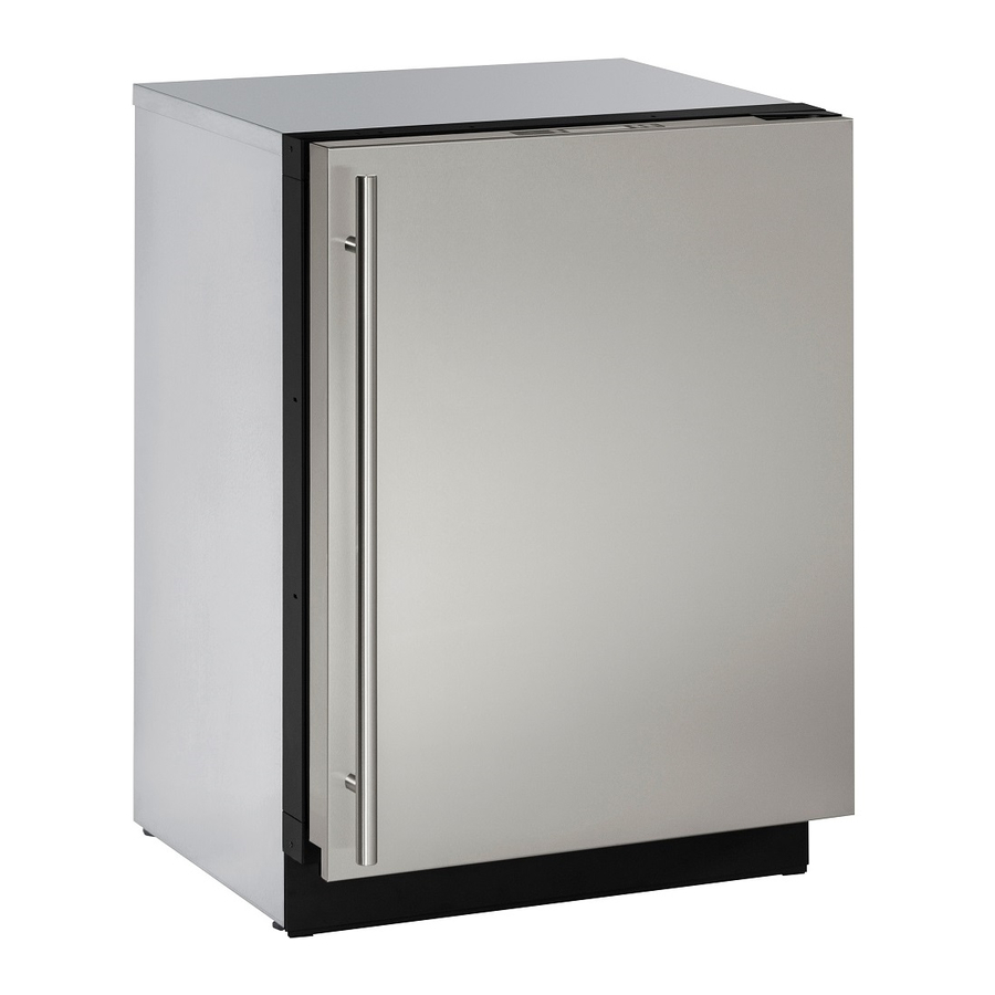
- Page 1 USER GUIDE SAFETY • INSTALLATION & INTEGRATION • OPERATING INSTRUCTIONS • MAINTENANCE • SERVICE RIGHT PRODUCT. RIGHT PLACE. RIGHT TEMPERATURE. SINCE 1962. Modular 3000 Series 3024R 24" Solid Door Refrigerator • •...
-
Page 2: Table Of Contents
USER GUIDE u-line.com SAFETY • INSTALLATION & INTEGRATION • OPERATING INSTRUCTIONS • MAINTENANCE • SERVICE Contents Intro Cleaning Condenser Extended Non-Use Safety Safety and Warning Service Disposal and Recycling Troubleshooting Warranty Installation Environmental Requirements Electrical Cutout Dimensions Product Dimensions Side by Side Installation... - Page 3 1. U-Line Customer Care must be contacted immediately at +1.800.779.2547. 2. Service or repairs performed on the unit without prior written approval from U-Line is not permitted. If the unit has been altered or repaired in the field without prior written approval from U-Line, claims will not be eligible.
-
Page 4: Safety And Warning
USER GUIDE u-line.com SAFETY • INSTALLATION & INTEGRATION • OPERATING INSTRUCTIONS • MAINTENANCE • SERVICE Safety and Warning DANGER NOTICE This unit contains R600a (Isobutane) which is a Please read all instructions before installing, flammable hydrocarbon. It is safe for regular operating, or servicing the appliance. -
Page 5: Disposal And Recycling
USER GUIDE u-line.com SAFETY • INSTALLATION & INTEGRATION • OPERATING INSTRUCTIONS • MAINTENANCE • SERVICE Disposal and Recycling DANGER RISK OF CHILD ENTRAPMENT. Before you throw away your old refrigerator or freezer, take off the doors and leave shelves in place so children may not easily climb inside. -
Page 6: Environmental Requirements
USER GUIDE u-line.com SAFETY • INSTALLATION & INTEGRATION • OPERATING INSTRUCTIONS • MAINTENANCE • SERVICE Environmental Requirements This model is intended for indoor/interior applications only and is not to be used in installations that are open/ exposed to natural elements. - Page 7 USER GUIDE u-line.com SAFETY • INSTALLATION & INTEGRATION • OPERATING INSTRUCTIONS • MAINTENANCE • SERVICE Electrical WARNING SHOCK HAZARD — Electrical Grounding Required. Never attempt to repair or perform maintenance on the unit until the electricity has been disconnected. Never remove the round grounding prong from the plug and never use a two-prong grounding adapter.
-
Page 8: Cutout Dimensions
SAFETY • INSTALLATION & INTEGRATION • OPERATING INSTRUCTIONS • MAINTENANCE • SERVICE Cutout Dimensions CUTOUT DIMENSIONS PREPARE SITE Your U-Line product has been designed exclusively for a built-in installation. When built-in, your unit does not Preferred location require additional air space for top, sides, or rear. -
Page 9: Product Dimensions
USER GUIDE u-line.com SAFETY • INSTALLATION & INTEGRATION • OPERATING INSTRUCTIONS • MAINTENANCE • SERVICE Product Dimensions 23-7/16" (590 mm)* 33-11/16" to 34-11/16" (856 mm to 881 mm) 3-5/8" to 4-5/8" 23-5/8" (600 mm) (92 mm to 118 mm) *Includes 3/4" (20 mm) integrated panel... -
Page 10: Side By Side Installation
USER GUIDE u-line.com SAFETY • INSTALLATION & INTEGRATION • OPERATING INSTRUCTIONS • MAINTENANCE • SERVICE Side-by-Side Installation Hinge-by-Hinge Installation (Mullion) When installing two units hinge-by-hinge, 13/16" (22 mm) OTHER SITE REQUIREMENTS is required for integrated models. Additional space may be Side-by-Side Installation needed for any knobs, pulls or handles installed. -
Page 11: Anti-Tip Bracket
USER GUIDE u-line.com SAFETY • INSTALLATION & INTEGRATION • OPERATING INSTRUCTIONS • MAINTENANCE • SERVICE Anti-Tip Bracket SIDE MOUNT Left Hinged Cabinet Right Hinged Cabinet CAUTION The anti-tip bracket must be installed to prevent the unit from tipping when doors are fully opened or excess weight is placed on the front of the unit. -
Page 12: General Installation
USER GUIDE u-line.com SAFETY • INSTALLATION & INTEGRATION • OPERATING INSTRUCTIONS • MAINTENANCE • SERVICE General Installation INSTALLATION 1. Plug in the power/electrical cord. LEVELING INFORMATION 1. Use a level to confirm 2. Gently push the unit into position. Be careful not to the unit is level. -
Page 13: Integrated Panel Dimensions
USER GUIDE u-line.com SAFETY • • OPERATING INSTRUCTIONS • MAINTENANCE • SERVICE INSTALLATION & INTEGRATION Integrated Panel Dimensions Integrated Panel Dimensions Metric measurements rounded and optimized. 3/4" BACK SURFACE MUST HAVE AMPLE FLAT SURFACE (20 mm) TO MOUNT OVERLAY PANEL FLAT AND WITHOUT... - Page 14 23-1/2" (595 mm) 3-1/2" (89 mm) solution for a handleless, integrated design that can be easily applied to your U-Line 3000 Series model. Consult your cabinet manufacturer for applicable design and installation details. The cabinet manufacturer’s solution to Wooden Insert...
- Page 15 USER GUIDE u-line.com SAFETY • • OPERATING INSTRUCTIONS • MAINTENANCE • SERVICE INSTALLATION & INTEGRATION Handleless Integrated Panel Dimensions 1/8" (3 mm) Top Design 1/4" (6 mm) 7/8" (22 mm) Ref. 2-3/8" R 5/8" (60 mm) (R16 mm) 23-1/2" (595 mm) 2-3/4"...
- Page 16 USER GUIDE u-line.com SAFETY • • OPERATING INSTRUCTIONS • MAINTENANCE • SERVICE INSTALLATION & INTEGRATION EXTENDED INTEGRATED PANEL NOTICE Due to differences in surrounding cabinetry the panel may not perfectly align with door. The procedure below is designed to provide a finished panel that seamlessly integrates with surrounding cabinetry.
- Page 17 USER GUIDE u-line.com SAFETY • • OPERATING INSTRUCTIONS • MAINTENANCE • SERVICE INSTALLATION & INTEGRATION Integrated Panel/Integrated Frame Integrated Panel U-Line U-Line Cabinet Unit Unit 3-5/16" (89 mm) 3-5/16" (89 mm) > 3-5/16" (> 89 mm) 4-5/16" (114 mm) 4-5/16" (114 mm)
- Page 18 USER GUIDE u-line.com SAFETY • • OPERATING INSTRUCTIONS • MAINTENANCE • SERVICE INSTALLATION & INTEGRATION Extended Integrated Panel Dimensions 3/4" BACK SURFACE MUST HAVE AMPLE FLAT SURFACE (20 mm) TO MOUNT OVERLAY PANEL FLAT AND WITHOUT INTERFERENCE 23-1/2" (595 mm) 32-7/8"...
-
Page 19: Integrated Grille / Plinth Dimensions
3. Apply double sided tape to the backside of the integrated grill (plinth strip/base fascia). Use the diagram below for reference. U-Line recommends ™ ™ tape, a high strength bonding tape. -
Page 20: Integrated Panel Installation
Clamp clamps. A robust NOTICE tape may also be If panel requires additional adjustment after used. U-Line removing clamps, slightly loosen each screw and recommends the adjust panel as necessary. Tighten screws upon use of bar clamps Door/Drawer completion. -
Page 21: Grille / Plinth Installation
USER GUIDE u-line.com SAFETY • INSTALLATION & INTEGRATION • OPERATING INSTRUCTIONS • MAINTENANCE • SERVICE Grille - Plinth Installation Installing the grille (plinth strip/base fascia) REMOVING AND INSTALLING GRILLE 1. Align slots in grille (plinth strip/base fascia) rail with (PLINTH STRIP/BASE FASCIA) -
Page 22: Door Swing
USER GUIDE u-line.com SAFETY • INSTALLATION & INTEGRATION • OPERATING INSTRUCTIONS • MAINTENANCE • SERVICE Door Swing For models that are installed adjacent to a wall, 1/4" (6 mm) clearance is recommended from wall on hinge side to allow the door to open 90°. Allow for additional space for any knobs or pulls installed on the integrated panel/ frame. -
Page 23: Door Stop
3. Once cover is removed, slide hinge pin into hole as shown. Pin should slide into place, stopping the door at Your U-Line unit was shipped to you with the optional 90° 90°; if the pin does not go into the hole shown, hold pin. - Page 24 USER GUIDE u-line.com SAFETY • INSTALLATION & INTEGRATION • OPERATING INSTRUCTIONS • MAINTENANCE • SERVICE Door Adjustments DOOR ALIGNMENT AND ADJUSTMENT Align and adjust the door if it is not level or is not sealing properly. If the door is not sealed, the unit may not cool...
- Page 25 USER GUIDE u-line.com SAFETY • INSTALLATION & INTEGRATION • OPERATING INSTRUCTIONS • MAINTENANCE • SERVICE 3. Using T-25 Torx bit loosen screw #1 and remove screw #2 on top and bottom hinge. Slide and remove the door from unit. Completely remove screw #1 on top and bottom.
-
Page 26: First Use
USER GUIDE u-line.com SAFETY • INSTALLATION & INTEGRATION • OPERATING INSTRUCTIONS • MAINTENANCE • SERVICE First Use All U-Line controls are preset at the factory. Initial startup requires no adjustments. NOTICE U-Line recommends allowing the unit to run overnight before loading with product. -
Page 27: Control Operation
USER GUIDE u-line.com SAFETY • INSTALLATION & INTEGRATION • OPERATING INSTRUCTIONS • MAINTENANCE • SERVICE Control Operation Zone Toggle Select Can be displayed in Celsius Power Down U-Select Lighting CONTROL FUNCTION GUIDE FUNCTION COMMAND DISPLAY/OPTIONS Press and hold Display will count down from 5 to off. - Page 28 USER GUIDE u-line.com SAFETY • INSTALLATION & INTEGRATION • OPERATING INSTRUCTIONS • MAINTENANCE • SERVICE ® U-SELECT CONTROL Food Storage Chart Digital Display Mode Food Types Deli Meats, Fish, Cheeses, Dairy, Butter, Garlic, The 3000 Series units are controlled by a feature rich, Oils, Nuts, Condiments advanced OLED display control unit.
-
Page 29: Interior Lighting
SAFETY • INSTALLATION & INTEGRATION • OPERATING INSTRUCTIONS • MAINTENANCE • SERVICE Interior Lighting Error Notification Your U-Line 3000 Series unit uses a state of the art LED The 3000 model series continuously monitors a series of lighting system. The 3036 model dual zone’s lighting can inputs and parameters to ensure proper and efficient be independently controlled or set as a group. - Page 30 CUSTOMER MENU 2. Press to scroll through available information. The 3000 Series of U-Line undercounter refrigeration appliances contains a feature rich customer menu. The 3. To return to the Customer Menu, press Customer Menu allows access to a series of advanced...
- Page 31 RETURN TO MENU LANGUAGES ENGLISH 4. Press to confirm your choice. Down The U-Line 3000 Series of models supports a number of Fahrenheit/Celsius display languages including English, Spanish, French and German. Select RETURN TO MENU 1. To change display language select Languages from the FARENHEIT/CELSIUS DEGREES = °F...
- Page 32 The Help screen displays the following: To access Factory Default: • Model. 1. Press to select “Factory Default”. • U-Line contact information. • Software version. 2. Press • Serial Number. To restore settings to their factory default: To exit the Help menu, press to select “Return to...
-
Page 33: Sabbath Mode
USER GUIDE u-line.com SAFETY • INSTALLATION & INTEGRATION • OPERATING INSTRUCTIONS • MAINTENANCE • SERVICE 7. Press to change “Off” to “On”. Sabbath Mode 8. Press to confirm your selection. The Display will fade out as the unit enters Sabbath Mode. -
Page 34: Airflow And Product Loading
Do not install the unit behind a door. When properly loaded, your U-Line unit will store up to 141 (12 oz. [330 ml]) cans or 100 (12 oz. [330 ml]) bottles. -
Page 35: Refrigerator Bins / Crisper
USER GUIDE u-line.com SAFETY • INSTALLATION & INTEGRATION • OPERATING INSTRUCTIONS • MAINTENANCE • SERVICE Cleaning Refrigerator Bins - Crisper Bins may be cleaned in a soapy warm water solution. A general household disinfectant, safe for plastics, may be REFRIGERATOR BIN INSTALLATION & REMOVAL used if necessary. -
Page 36: Maintenance
USER GUIDE u-line.com SAFETY • INSTALLATION & INTEGRATION • OPERATING INSTRUCTIONS • • SERVICE MAINTENANCE Cleaning Integrated Models To clean integrated panels, use household cleaner per the EXTERIOR CLEANING cabinet manufacturer’s recommendation. Stainless Models Stainless door panels and handles can discolor when... - Page 37 USER GUIDE u-line.com SAFETY • INSTALLATION & INTEGRATION • OPERATING INSTRUCTIONS • • SERVICE MAINTENANCE NOTICE The drain pan was not designed to capture the water created when manually defrosting. To prevent water from overflowing the drain pan and possibly damaging water sensitive flooring, the unit must be removed from cabinetry.
-
Page 38: Cleaning Condenser
USER GUIDE u-line.com SAFETY • INSTALLATION & INTEGRATION • OPERATING INSTRUCTIONS • MAINTENANCE • SERVICE Cleaning Condenser INTERVAL - EVERY SIX MONTHS To maintain operational efficiency, keep the front grille (plinth strip/base fascia) free of dust and lint, and clean the condenser when necessary. -
Page 39: Extended Non-Use
If the unit will be exposed to temperatures of 40°F (5°C) or less, the steps above must be followed. For questions regarding winterization, please call U-Line at +1.800.779.2547. CAUTION Damage caused by freezing temperatures is not covered by the warranty. -
Page 40: Troubleshooting
• Compressor: The compressor makes a hum or pulsing sound that may be heard when it operates. BEFORE CALLING FOR SERVICE If you think your U-Line product is malfunctioning, read • Evaporator: Refrigerant flowing through an evaporator the CONTROL OPERATION section to clearly understand may sound like boiling liquid. - Page 41 12H+ temperature +10° and sealing. Contact properly. For other error codes contact over set point for Customer Care if U-Line Customer Service. over 12 hours. persistent. Product Is Because product in contact with the rear wall (L) (R) Temp Lo...
- Page 42 USER GUIDE u-line.com SAFETY • INSTALLATION & INTEGRATION • OPERATING INSTRUCTIONS • MAINTENANCE • SERVICE 6. After 24 hours, check the temperature of the water. If required, adjust the temperature control in a small increment (see CONTROL OPERATION). Causes which affect the internal temperatures of the cabinet include: •...
-
Page 43: Warranty 1
2. During the initial one year warranty period (two years on Modular 3000 Series) for all U-Line products U-Line 5. U-Line products are designed to operate in ambient shall: (1) repair any product or replace any part of a temperatures between 50°F and 100°F unless... - Page 44 ARE DISCLAIMED. U-Line’s sole liability and your exclusive remedy under this warranty are set forth in the paragraphs above. U-Line shall have no liability whatsoever for any incidental, consequential or special damages arising from the sale, use or installation of...
Need help?
Do you have a question about the 3024R and is the answer not in the manual?
Questions and answers