Advertisement
1
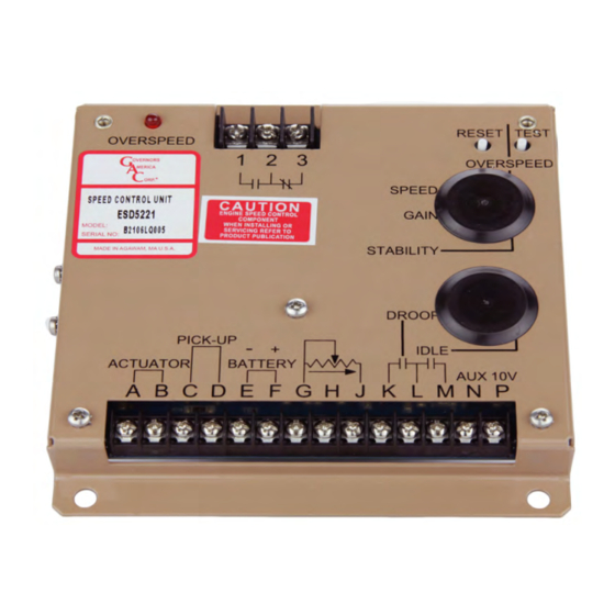
INTRODUCTION
The ESD5550/5570 series speed control unit is an all electronic device designed to
control engine speed with fast and precise response to transient load changes. This
closed loop control, when connected to a proportional electric actuator and supplied
with a magnetic speed sensor signal, can control a wide variety of engines in an iso-
chronous or droop mode. Designed for high reliability and built ruggedly to withstand
the engine environment. ESD5550/5570 Series speed control unit features include:
•
Simple installation
•
Starting Fuel and Speed Ramping adjustments to minimize engine exhaust
smoke prior to attaining engine operating speed
•
Adjustable droop and idle operation
•
Inputs for accessories used in multi-engine or special applications
•
Protection against reverse battery voltage, transient voltages, accidental short
circuit of the actuator and fail safe design in the event of loss of speed sensor
signal or battery supply.
•
Light Force Actuation (ESD5570 only)
The ESD5550/5570 Series speed control unit is compatible with all GAC proportional
actuators (except ACB2001). When paired with a GAC ADC100 Series electric ac-
tuator, DROOP adjustment range is less due to the ADC100's low current demand.
2
SPECIFICATIONS
Performance
Isochronous / Steady State
Stability
Speed Range / Governor
Speed Drift with Temperature
Idle Adjust CW
Idle Adjust CCW
Droop Range
Droop Adjustment MAX
(K-L Jumpered)
Droop Adjustment MIN
(K-L Jumpered)
Remote Variable Speed Range
Speed Trim Range
Terminal Sensitivity
InPUT / oUTPUT
Operating Voltage
Polarity
Power Consumption
Actuator Current Range at 77 °F
(25 °C) - Inductive Load
Speed Sensor Signal
Speed Switch Relay Contacts
(N.O. and N.C.)
ESD5550 & ESD5570 Series
Speed Control Unit
± 0.25 % or better
1 K - 7.5 K Hz continuous
60 % of set speed
Less than 1200 Hz
1 - 5 % regulation
400 Hz, ±75 Hz per 1 A change
415 Hz, ±75 Hz per 1 A change
500 - 7.5 Hz or any part thereof
J
100 Hz ±15 Hz/V @ 5.0 kΩ Impedance
L
735 Hz ±60 Hz/V @ 65 kΩ Impedance
N
148 Hz ±10 Hz/V @1 MΩ Impedance
P
10 V DC Supply @ 20 mA MAX
12 VDC or 24 VDC (Transient and
Reverse Voltage Protected)*
Negative Ground (Case Isolated)
50 mA continuous plus actuator current
Minimum 2.5 A
0.5 to 120 V RMS
Vibration
Testing
±1 % MAX
Ambient Temperature Range
Relative Humidity
Shock
All Surface Finishes
Agency
Dimension
± 200 Hz
Weight
Mounting
10 A Peak**
* Protected against reverse voltage by a series diode. A 15 amp fuse must be installed in
the positive battery lead.
** Protected against short circuit to actuator (shuts off current to actuator), unit automati-
10 A
cally turns back on when short is removed.
1
ESD5550-5570 Series Speed Control Unit 1-2021-E1 PIB1003
Governors America Corp. © 2021 Copyright All Rights Reserved
reLIaBILITY
100% Functional Testing
envIronmenTaL
-40° to 85 °C [-40° to 180 °F]
Fungus Proof, Corrosion Resistant
comPLIance / STanDarDS
CE, RoHS, Lloyds Register,
DNV/GL, Bureau Vertas
PHYSIcaL
See Section 3, Installation
Any position, vertical preferred
5 g @ 20 - 500 Hz
up to 95 %
20 g @ 11 ms
1.8 lbf [0.82 kgf]
Advertisement
Table of Contents

Subscribe to Our Youtube Channel
Related Manuals for GAC ESD5570 Series


Summary of Contents for GAC ESD5570 Series
- Page 1 • Light Force Actuation (ESD5570 only) The ESD5550/5570 Series speed control unit is compatible with all GAC proportional actuators (except ACB2001). When paired with a GAC ADC100 Series electric ac- tuator, DROOP adjustment range is less due to the ADC100’s low current demand.
-
Page 2: Installation
INSTAllATION Take into account the following preferences when mounting the speed controller: Vertical orientation allows fluids to drain in moist environments. Avoid extreme heat Mount in a cabinet, engine enclosure, or sealed metal box. Dimensions [mm] WIRINg TermInaL DefInITIon noTeS use #16 [1.3 mm ] or larger wire. - Page 3 WIRINg (CONTINUED) An overspeed shutdown device, independent of the governor system, must be provided to prevent loss of engine control which may cause personal injury or equipment damage. Do not rely exclusively on the governor system to prevent over- speed. A secondary shutoff device such as a fuel solenoid must be used. When wiring eSD55XX Series controllers: Magnetic speed sensor wires connected to Terminals C and D MuST BE TWISTED AND/OR SHIELDED for their entire length.
-
Page 4: Adjustment / Switch
Terminals N and P. This is required to match the voltage levels between the speed control unit and the synchronizer. acceSSorY SUPPLY Terminal P supplies +10 volt regulated supply to provide power to GAC governor system accessories. up to 20 mA of current can be drawn from this supply. Ground reference is Terminal G. - Page 5 ADJUSTMENTS - CONTINUED aDJUSTInG overSPeeD The overspeed relay output terminals offer both normally open and normally closed contacts. When the engine is running at the desired speed, push and hold the TEST button. SPEED Rotate the OVERSPEED adjustment CCW until the red OVERSPEED LED lights and the OVERSPEED relay energizes.
- Page 6 Though a wide range of droop is available with the internal control, droop level requirements of 10% are unusual. If droop levels experi- enced are higher or lower than those required, contact GAC for assistance. WIDe ranGe remoTe varIaBLe SPeeD oPeraTIon Remote variable speed can be obtained with the an external potentiometer.
-
Page 7: System Troubleshooting
SySTEM TROUblESHOOTINg InSUffIcIenT maGneTIc SPeeD SIGnaL A strong magnetic speed sensor signal eliminates the possibility of missed or extra pulses. The speed control unit governs well with 0.5 volts RMS speed sensor signal. A speed sensor signal of 3 volts RMS or greater at governed speed is recommended. Measurement of the signal is made at Terminals C and D. - Page 8 SySTEM TROUblESHOOTINg (CONTINUED) UnSaTISfacTorY Performance SYmPTom normaL reaDInG ProBaBLe caUSe Engine Overspeeds Do Not Crank. Apply DC power to After the actuator goes to full fuel, disconnect the speed sensor at Terminal the governor system. C & D. If the actuator is still at full fuel-speed then the speed control unit is defective.
Need help?
Do you have a question about the ESD5570 Series and is the answer not in the manual?
Questions and answers