Advertisement
Quick Links
ESD-5550/5570 Series - Speed Control Unit
Table 1.
Starting Fuel
Control
ESD-5550
•
ESD-5555
•
ESD-5556
•
ESD-5570
•
INSTALLATION
The speed control unit is rugged enough to be placed in a control cabinet or engine mounted
enclosure with other dedicated control equipment. If water, mist, or condensation may come in
contact with the controller, it should be mounted vertically. This will allow the fluid to drain away
from the speed control unit. Extreme heat should be avoided.
An overspeed shutdown device, independent of the governor system, should be provided to
prevent loss of engine control, which may cause personal injury or equipment damage. Do not rely
exclusively on the governor system electric actuator to prevent overspeed.
A secondary shutoff device, such as a fuel solenoid, must be used.
Technical Information
ESD-5550/5570 Series Speed Control Units
Single Element
Speed
Speed Switch
Ramping
(Overspeed)
•
•
•
•
•
•
•
2 Element Speed
Switch
For Use with a
(Overspeed &
Light Force
Crank
Actuator
Termination)
•
•
•
Interator Wind-
Up Protection
•
•
Advertisement

Related Manuals for GAC ESD-5550 Series


Summary of Contents for GAC ESD-5550 Series
- Page 1 Technical Information ESD-5550/5570 Series - Speed Control Unit Table 1. ESD-5550/5570 Series Speed Control Units 2 Element Speed Single Element Switch For Use with a Starting Fuel Speed Interator Wind- Speed Switch (Overspeed & Light Force Control Ramping Up Protection (Overspeed) Crank Actuator...
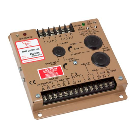
- Page 2 Technical Information WIRING Basic electrical connections are illustrated in Diagram 2 (for the ESD-5550, ESD-5555 and the ESD-5570) and Diagram 3 (for the the ESD-5556 only). Actuator and battery connections to Terminals A, B, E, and F should be #16 AWG (1.3 mm ) or larger.
- Page 3 Technical Information Adjusting Crank Termination (ESD-5556 only) To protect the engine from harm the CRANK TERMINATION adjustment is factory set at full CCW [Lowest Setting]. To adjust CRANK TERMINATION speed setting, rotate the CRANK adjustment to full CW. Crank the engine and simultaneously turn the CRANK adjustment slowly CCW until the proper crank termination speed is reached.
- Page 4 Technical Information GAIN and STABILITY adjustments may require minor changes after engine load is applied. Normally, adjustments made at no load achieve satisfactory performance. A strip chart recorder can be used to further optimize the adjustments. If instability cannot be corrected or further performance improvements are required, refer below to the SYSTEM TROUBLESHOOTING section.
- Page 5 7000 Hz. Accessory Supply The +10 VDC regulated supply, Terminal P, can be utilized to provide power to GAC governor system accessories. Up to 20 mA of current can be drawn from this supply. Ground reference is Terminal G.
-
Page 6: Specifications
Technical Information To maintain engine stability at the minimum speed setting, a small amount of droop can be added turn the DROOP adjustment CW. At the maximum speed setting the governor performance will be near isochronous, regardless of the droop adjustment setting. Contact for assistance if difficulty is experienced in obtaining the desired variable speed governing performance. -
Page 7: Input Power
Technical Information Terminal Sensitivity J ..............100 Hz., ± 15 Hz / Volt @ 5.0 K Impedance L ..............735 Hz., ± 60 Hz / Volt @ 65 K Impedance N ..............148 Hz., ± 10 Hz / Volt @ 1 Meg Impedance P .................. - Page 8 Technical Information Diagramm2 for ESD-5550, ESD-5555 and ESD-5570 only...
- Page 9 Technical Information Diagramm for ESD-5556 only...
-
Page 10: System Troubleshooting
Technical Information SYSTEM TROUBLESHOOTING SYSTEM INOPERATIVE If the engine governing system does not function, the fault may be determined by performaning the voltage tests described in Steps 1, 2, 3 and 4. [+] and [-] refer to meter polarity. Should normal values be indicated as a result of following the troubleshooting steps, the fault may be with actuator or the wiring to the actuator. - Page 11 All GAC speed control sensors contain filters and shielding designed to protect the unit’s sensitive circuits from moderate external interfering sources. Although it is difficult to predict levels of...
- Page 12 Technical Information Slow instability can have many causes. Adjustment of the GAIN and STABILITY usually cures most situations by matching the speed control unit dynamics. If this is unsuccessful, the dead time compensation can be modified. Add a capacitor from posts E2 to E3 (negative on E2). Post locations are illustrated in Diagram 1.
Need help?
Do you have a question about the ESD-5550 Series and is the answer not in the manual?
Questions and answers