Table of Contents
Advertisement
Quick Links
1
OVERVIEW
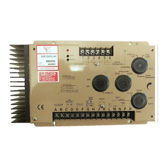
The eSD5300 Series Speed Control units are designed to precisely
control engine speed and provide fast, precise response to transient
engine loads. The eSD5330 and 5340 speed control can be used with
all GAC Actuators, including the ACB2001. A complete, closed-loop
control system is formed with the addition of a magnetic pickup signal
sensing engine speed and 24 V DC power.
◊
Two-element speed switch
◊
Speed ramping idle to operating speed
◊
Starting fuel control for lower engine exhaust emissions
◊
Unique actuator power drive circuit
◊
Accessory inputs for load sharing
◊
Variable speed governing
◊
Protection against reverse battery and transient voltage
◊
Advanced startup circuit for large-bore engines (eSD5340)
2
SPECIFICATIONS
Performance
Isochronous Operation
Speed Range / Governor
Speed Drift with
Temperature
Idle Speed Adjust Range
Droop Range
Speed Trim Range
Remote Variable Speed
Range
Starting Fuel Adjustment
0.0 - 1.5 A
0.3 - 5.0 A
Overspeed Set Point
Crank Termination Set
Point
Terminal Sensitivity
H
M
K
N
reLIaBILITY
Vibration
Shock
Testing
ESD5300 Series
Speed Control Unit
1.0 - 7.5 KHz Continuous
± 1% MAX
25 - 85 % of rated speed
0 - 5 % for a 1.5 A actuator
current change
ACCel: 266 Hz/s - 1300 Hz/s
DeCel: 250 Hz/s - 1000 Hz/s
120, 175, 225, 275 Actuators / SW2-7
(24 V DC Only) 2001 Actuator / SW2-7
2330 Hz - 8500 Hz
200 Hz - 2050 Hz
105 Hz, ±15 Hz/V @ 5 kΩ
130 Hz, ±15 Hz/V @ 1 MΩ
685 Hz, ±40 Hz/V @ 326 kΩ
1000 Hz, ±50 Hz/V @ 8 k Ω
1 G, 20 - 100 Hz
10 G (11 ms)
100 % Functional Testing
± 0.25 %
Supply
Maximum Continuous
Supply
Polarity
Power Consumption
± 200 Hz
Speed Signal Range
MAX Actuator Peak Current
MAX Current, Relay Contact
(Terminals 1 - 6) Rating
OFF
Chopping Frequency Range
ON
Ambient Temperature
Relative Humidity
All Surface Finishes
Impedance
Impedance
Agency
Impedance
Impedance
Dimension
Weight
Mounting
1
Governors America Corp. © 2020 Copyright All Rights Reserved
InPUT / oUTPUT
24 V DC Battery Systems
Reverse Voltage Protected)
100 mA (no actuator current)
envIronmenTaL
-40 to 85 °C (-40 to 185 °F)
and Corrosion Resistant
comPLIance / STanDarDS
Ce and RoHS Requirements
PHYSIcaL
See Section 4, Installation
Any position, vertical preferred
ESD5300 Speed Control Unit 09-2020-H
(Transient and
32 V DC
Negative Ground
(Case Isolated)
1.0 - 50 V AC
15 A
6 A
60 - 380 Hz
up to 95 %
Fungus Proof
3 lbf ( 1.36 kgf )
PIB1041
Advertisement
Table of Contents

Related Manuals for GAC ESD5300 Series


Summary of Contents for GAC ESD5300 Series
- Page 1 ESD5300 Series Speed Control Unit OVERVIEW The eSD5300 Series Speed Control units are designed to precisely control engine speed and provide fast, precise response to transient engine loads. The eSD5330 and 5340 speed control can be used with all GAC Actuators, including the ACB2001. A complete, closed-loop control system is formed with the addition of a magnetic pickup signal sensing engine speed and 24 V DC power.
-
Page 2: Installation
INSTAllATION The eSD5300 speed controller can be placed in a control cabinet or engine mounted enclosure with other control equipment. If water, mist, or condensation can come in contact with the controller, it should be mounted vertically, to allow any accumulated fluids to drain away from the unit. - Page 3 WIRINg (CONTINUED) ESD5300 Speed Control Unit 09-2020-H PIB1041 Governors America Corp. © 2020 Copyright All Rights Reserved...
-
Page 4: Dip Switches
335, 2001 = ON When switch C2 is ON, the Soft Coupling feature is enabled. SW2 Switches 5-8 must be set to match the actuator being used in the application. Contact GAC for questions. START ThE ENgINE If crank termination occurs too quickly preventing the engine from starting, turn the crank termination adjustment clockwise (CW). The actuator should snap to full fuel until the engine starts and run at a low idle setting. -
Page 5: Initial Adjustments
INITIAl ADjUSTmENTS Once the engine is running at operating speed and at no load, the following governor performance adjustment can be made to increase engine stability. ParameTer aDJUSTmenT ProceDUre Rotate the GAIN adjustments CW until instability develops. Gradually move the adjustment CCW until stability returns. (GAIN) Move the adjustment one division further CCW to ensure stable performance. - Page 6 InTernaL SPeeD ramPInG fUncTIon each time the eSD5300 Series controller is started the speed ramping function operates by taking control of the engine at near idle po- sition and automatically raises the engine speed until the speed set point is reached. The acceleration time is controlled by the acceler- ation control.
- Page 7 ADDITIONAl FEATURES (CONTINUED) aDJUSTaBLe cHoPPInG freQUencY The actuator chopping frequency can be varied using the potentiometer labeled CF ADJ. This chopping frequency applied to the actuator provides an additional stability enhancement as the dither shakes the actuator to overcome static friction and ensure its immediate response. overSPeeD monITor The overspeed monitor circuit trip point is set by the multi-turn potentiometer.
-
Page 8: Accessory Input
SUPPLY The +10 V regulated supply, Terminal l, can be utilized to provide power to GAC governor system accessories. Up to 40 mA of current can be drawn from this supply. The ground reference for this supply is Terminal G. - Page 9 The governor system can be adversely affected by large interfering signals that are conducted through the cabling or through direct radiation into the control circuits. All GAC speed control sensors contain filters and shielding designed to protect the units sensitive circuits from moderate external interfering sources.
Need help?
Do you have a question about the ESD5300 Series and is the answer not in the manual?
Questions and answers