Advertisement
1
INTRODUCTION
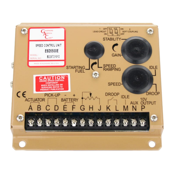
The ESD5500E Series Speed Control Unit is an all-electronic device designed to control
engine speed quickly and precisely in response to transient load changes.
The ESD5500E controls a wide variety of engines in isochronous or droop mode when
connected to a proportional electric actuator and magnetic speed sensor. The ruggedly
built ESD5500E series is designed to withstand the engine environment. Light-Force
variations are available.
moDeL
ESD5500E
Multi-VDC / Standard Unit
ESD5520E
Multi-VDC / Light-Force (Low-Current Optimized PID) / Enhanced Droop
Multi-VDC / Light-Force (Low-Current Optimized PID) / Enhanced Droop
ESD5522E
for Cummins EFC Forward Acting (Normally Closed)
Multi-VDC / Light-Force (Low-Current Optimized PID) / Anti-Windup
ESD5526E
Circuit (Gaseous) / Recommended for T1/T2 ATBs
Multi-VDC / Anti-Windup Circuit (Gaseous) / Recommended for T3/T4
ESD5528E
ATBs
2
SPECIFICATIONS
Performance
Isochronous Operation
Speed Range / Governor
Speed Drift with Temperature
Idle Adjust Clockwise
Idle Adjust Counterclockwise
Droop Range
Droop Adjust Maximum
(K-L jumpered)
Droop Adjust Minimum
(K-L jumpered)
Speed Trim Range
Remote Variable Speed
Range
Terminal Sensitivity
J
L
N
P
InPut / outPut
DC Supply
Polarity
Power Consumption
Speed Signal Range
Speed Sensor Signal
Actuator Current Range**
(77°F (25°C))
* Protected against short circuit to actuator (shuts off current to actuator), unit automatically turns on when short is removed.
** Protected against reverse voltage by a series diode. A 15 A fuse must be installed in the positive battery lead.
ESD5500E Series
Speed Control Unit
DeScrIPtIon
± 0.25 % or better
1 - 7.5 kHz Continuous
±1 % MAX
60 % of Set Speed
Less than 1200 Hz
1 - 5 % regulation
400 Hz ±75 Hz per 1.0 A change
15 Hz ±75 Hz per 1.0 A change
500 - 7.5 kHz
100 Hz ±15 Hz/Volt @ 5.0 kΩ Impedance
735 Hz ±60 Hz/Volt @ 65.0 kΩ Impedance
148 Hz ±10 Hz/Volt @ 1 MΩ Impedance
10 V DC Supply @ 20 mA MAX
12 V DC and 24 V DC Battery Systems
Transient and Reverse Voltage Protected*
Negative Ground (Case Isolated)
50 mA continuous plus actuator current
1.0 - 50 V AC
1.0 - 120 V RMS
Minimum 1.0 A
Nominal 7.0 A
Peak 10.0 A
Vibration
Testing
Ambient Temperature
Relative Humidity
All Surface Finishes
Agency
± 200 Hz
Dimension
Weight
Mounting
1
Governors America Corp. © 2020 Copyright All Rights Reserved
reLIaBILItY
100 % Functionally Tested
envIronmentaL
-40° to 85 °C (-40° to 180 °F)
Fungus Proof, Corrosion Resistant
comPLIance / StanDarDS
CE (EN55011, EN50081-2, EN50082-2),
RoHS, Lloyds Register,
DNV/GL, Bureau Veritas
PHYSIcaL
See Wiring Diagram and Outline
Any position, vertical preferred
ESD5500E Series Speed Control Unit 9-2020-F PIB1002
1 g @ 20-100 Hz
up to 95 %
1.20 lbf (0.54 kgf)
Advertisement
Table of Contents

Related Manuals for GAC ESD5500E Series


Summary of Contents for GAC ESD5500E Series
- Page 1 Speed Control Unit INTRODUCTION The ESD5500E Series Speed Control Unit is an all-electronic device designed to control engine speed quickly and precisely in response to transient load changes. The ESD5500E controls a wide variety of engines in isochronous or droop mode when connected to a proportional electric actuator and magnetic speed sensor.
- Page 2 Avoid Extreme Heat Mount in a cabinet, engine enclosure, or sealed metal box. Dimensions [mm] WIRINg ESD5500E Series Speed Control Unit 9-2020-F PIB1002 Governors America Corp. © 2020 Copyright All Rights Reserved...
- Page 3 Load Sharing/Synchronizing, 0-10 V DC (5V Nominal, Reversed, 148 Hz/V). Shielded cabling recommended. Accessory Power Supply 10 V DC Output To Power GAC Load Sharing and Synchronizing Modules aDDInG a PotentIometer Use a single remote speed adjustment potentiometer to adjust engine speed.
- Page 4 CURRENTS ABOVE 5A BATTERY OR ACTUATOR ACTUATOR CURRENTS ABOVE 5A GROUND REFERENCE MAGNETIC GROUND REFERENCE ESD5500E Series Speed Control Unit 9-2020-F PIB1002 MAGNETIC CLOSE FOR DROOP PICK-UP Governors America Corp. © 2020 Copyright All Rights Reserved CLOSE FOR DROOP PICK-UP...
-
Page 5: Methods Of Operation
A B C D E F G H J L M N P Ø0.266 (6,6) WD554 ACCESSORY POWER SUPPLY ACCESSORY INPUT ESD5500E Series Speed Control Unit 9-2020-F PIB1002 Governors America Corp. © 2020 Copyright All Rights Reserved ADD JUMPER FOR 12V... - Page 6 SuPPLY The +10 volt regulated supply, Terminal P, can be utilized to provide power to GAC governor system accessories. Up to 20 mA of current can be drawn from this supply. Ground reference is Terminal G.
-
Page 7: Conversion Formulas
An additional fixed resistor may be placed across the potentiometer to obtain the exact desired range. Connect the speed note range potentiometer as shown to the right using Terminals G and J. Contact GAC for assistance if you experience difficulty obtaining the desired variable speed governing performance. -
Page 8: Troubleshooting
If throttle is slightly erratic, but performance is fast, move switch C1 to the OFF position. ESD5500E Series Speed Control Unit 9-2020-F PIB1002 Governors America Corp. © 2020 Copyright All Rights Reserved... - Page 9 Engine remains output, Terminals A & linkage interference. below desired B, while running under governed speed governor control. SPEED parameter set too low ESD5500E Series Speed Control Unit 9-2020-F PIB1002 Governors America Corp. © 2020 Copyright All Rights Reserved...
Need help?
Do you have a question about the ESD5500E Series and is the answer not in the manual?
Questions and answers