Table of Contents
Advertisement
Quick Links
INSTALLATION/OPERATION &
AJ-64CE
AJ-64CS
AJ-64CGP
October 06, 2015
P/N 7610-002-30-93 (Revision K)
TECHNICAL MANUAL
FOR JACKSON MODELS:
AND ASSOCIATED OPTION PACKAGES INCLUDING:
D226 EXTERNAL STEAM BOOSTER
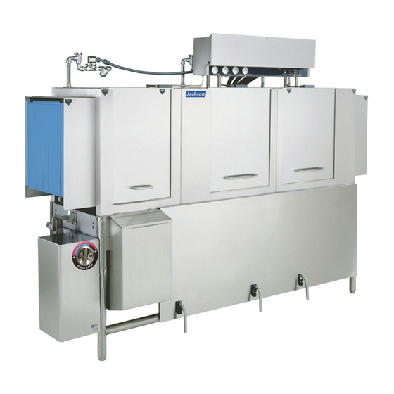
AJ-64 SERIES RACK CONVEYOR DISHMACHINE
AJ-86CE
AJ-86CGP
AJ-86CS
SIDE LOADER
AJ-100CE
AJ-100 CGP
Jackson WWS ,INC.
P.O. Box 1060
Barbourville, KY. 40906
(606) 523-9795
Fax: (606) 523-9196
www.jacksonwws.com
Advertisement
Table of Contents

Subscribe to Our Youtube Channel
Related Manuals for Jackson AJ-64CGP


Summary of Contents for Jackson AJ-64CGP
- Page 1 AJ-64 SERIES RACK CONVEYOR DISHMACHINE INSTALLATION/OPERATION & TECHNICAL MANUAL FOR JACKSON MODELS: AJ-64CE AJ-86CE AJ-100CE AJ-64CS AJ-86CGP AJ-100 CGP AJ-64CGP AJ-86CS AND ASSOCIATED OPTION PACKAGES INCLUDING: SIDE LOADER D226 EXTERNAL STEAM BOOSTER Jackson WWS ,INC. P.O. Box 1060 Barbourville, KY. 40906...
- Page 2 The warranty registration card supplied with the machine must be returned to Jackson WWS within 30 days to validate the warranty. REPLACEMENT PARTS WARRANTY Jackson replacement parts are warranted for a period of 90 days from the date of installation or 180 days from the date of shipment from the factory, which ever occurs first.
- Page 3 STOP! PARE! ARRET! C ALL 1- 888- 800- 5672 TO REG I STER THI S PRO DUC T! FAI LURE TO DO SO W I LL VO I D THE W ARRANTY! LLAM E AL 1- 888- 800- 5672 PARA REG I STRAR ESTE PRO DUC TO ! AL NO HAC ERLO LA G ARANTI A SERA ANULADA! S.
- Page 4 Changed the part from a weldment (05700-021-67-50) to a 10-09-2009 8044 casting (09515-003-58-12). 08-12-2013 QOF NDB-219 Updated Manufacturer information. Updated Jackson Logo 09-15-2014 Updated temperatures on pg's 7, 8, 13, 14, 19, and 20. 02-06-2014 Updated drawing on pg. 39 Updated rack rail assembly on pg. 97...
- Page 5 CE = Electrically heated, hot water sanitizing machine CS = Steam heated, hot water sanitizing machine CGP = Gas heated, hot water sanitizing machine Jackson WWS ,INC. provides technical support for Model: all of the dishmachines detailed in this manual. We strongly recommend that you refer to this manual Serial No.:...
-
Page 6: Table Of Contents
TABLE OF CONTENTS SECTION DESCRIPTION PAGE SPECIFICATION INFORMATION Operating Characteristics Electrical Requirements D226 Steam Booster Parameters AJ-64 Electric - Left to Right AJ-64 Electric - Right to Left AJ-64 Gas - Left to Right AJ-64 Gas - Right to Left AJ-64 Steam - Left to Right AJ-64 Steam - Right to Left AJ-86 Electric - Left to Right... - Page 7 TABLE OF CONTENTS PARTS PARTS SECTION AJ-64 Control Box Assembly AJ-86/AJ-100 Control Box Assembly Motor Overload Chart Heater Box Assembly Heater Assembly Frame Weldments/Front Dress Panels Prewash Plumbing Assembly Incoming Plumbing Assembly Rinse Header Plumbing Assembly (CGP Models) External Electric Booster Option Incoming Plumbing External Electric Booster Option Outlet Plumbing WPRK Plumbing Option 3/4”...
- Page 8 TABLE OF CONTENTS ELECTRICAL SCHEMATICS VII. ELECTRICAL SCHEMATICS AJ-64CE 208-230 Volt, 60 Hz, 1 Phase Primary Side 208-230 Volt, 60 Hz, 1 Phase Secondary Side 208-230 Volt, 60 Hz, 3 Phase Primary Side 208-230 Volt, 60 Hz, 3 Phase Secondary Side 460-575-600 Volt, 60 Hz, 3 Phase Primary Side 460-575-600 Volt, 60 Hz, 3 Phase Secondary Side AJ-64CS...
-
Page 9: Specification Information
SECTION 1: SPECIFICATION INFORMATION... -
Page 10: Operating Characteristics
SECTION 1: SPECIFICATION INFORMATION OPERATING CHARACTERISTICS RACKS PER HOUR: FLOWRATE (GPM): AJ-64-86-100CE/CS/CGP AJ-64-86-100CE/CS/CGP DISHES OR GLASSES PER HOUR: STEAM COIL TANK HEAT (CS MODELS ONLY): AJ-64-86-100CE/CS/CGP 7200 STEAM INLET PRESSURE (PSIG) 10-20 STEAM CONNECTION NPT 3/4” CONSUMPTION @ 15 PSIG (lbs/hr): PREWASH TANK CAPACITY (GALLONS): AJ-64-86-100CS/CSL AJ-86CE/CS/CGP... -
Page 11: Electrical Requirements
SECTION 1: SPECIFICATION INFORMATION ELECTRICAL REQUIREMENTS AJ-64CE MODELS AJ-86CE MODELS TYPICAL TYPICAL TOTAL ELECTRICAL TOTAL ELECTRICAL VOLTS AMPS CIRCUIT VOLTS AMPS CIRCUIT 139 A 175 AMP 145 A 200 AMP 128 A 175 AMP 134 A 175 AMP 82 A 110 AMP 86 A 110 AMP... -
Page 12: D226 Steam Booster Parameters
* - Indicates typical design criteria but is subject to change TYPICAL TOTAL ELECTRICAL without notice. For more information, contact you authorized VOLTS AMPS CIRCUIT Jackson service representative. 28 A 35 AMP 28 A 35 AMP WATER OUTLET SAFETY VALVE 18 A 25 AMP... -
Page 13: Electric - Left To Right
SECTION 1: SPECIFICATION INFORMATION AJ-64 ELECTRIC - LEFT TO RIGHT... -
Page 14: Electric - Right To Left
SECTION 1: SPECIFICATION INFORMATION AJ-64 ELECTRIC - RIGHT TO LEFT... -
Page 15: Gas - Left To Right
SECTION 1: SPECIFICATION INFORMATION AJ-64 GAS - LEFT TO RIGHT AJ-64 Conveyor Series Technical Manual 7610-003-30-93 Issued: 05-02-2006 Revised: 09-29-2007... -
Page 16: Gas - Right To Left
SECTION 1: SPECIFICATION INFORMATION AJ-64 GAS - RIGHT TO LEFT... -
Page 17: Steam - Left To Right
SECTION 1: SPECIFICATION INFORMATION AJ-64 STEAM - LEFT TO RIGHT... -
Page 18: Steam - Right To Left
SECTION 1: SPECIFICATION INFORMATION AJ-64 STEAM - RIGHT TO LEFT... -
Page 19: Electric - Left To Right
SECTION 1: SPECIFICATION INFORMATION AJ-86 ELECTRIC - LEFT TO RIGHT... -
Page 20: Electric - Right To Left
SECTION 1: SPECIFICATION INFORMATION AJ-86 GAS - LEFT TO RIGHT... -
Page 21: Gas - Left To Right
SECTION 1: SPECIFICATION INFORMATION AJ-86 GAS - LEFT TO RIGHT... -
Page 22: Gas - Right To Left
SECTION 1: SPECIFICATION INFORMATION AJ-86 GAS - RIGHT TO LEFT... -
Page 23: Steam - Left To Right
SECTION 1: SPECIFICATION INFORMATION AJ-86 STEAM - LEFT TO RIGHT... -
Page 24: Steam - Right To Left
SECTION 1: SPECIFICATION INFORMATION AJ-86 STEAM - RIGHT TO LEFT... -
Page 25: Electric - Left To Right
SECTION 1: SPECIFICATION INFORMATION AJ-100 ELECTRIC - LEFT TO RIGHT... -
Page 26: Electric - Right To Left
SECTION 1: SPECIFICATION INFORMATION AJ-100 ELECTRIC - RIGHT TO LEFT... -
Page 27: Gas - Left To Right
SECTION 1: SPECIFICATION INFORMATION AJ-100 GAS - LEFT TO RIGHT... -
Page 28: Gas - Right To Left
SECTION 1: SPECIFICATION INFORMATION AJ-100 GAS - RIGHT TO LEFT... -
Page 29: Steam - Left To Right
SECTION 1: SPECIFICATION INFORMATION AJ-100 STEAM - LEFT TO RIGHT... -
Page 30: Steam - Right To Left
SECTION 1: SPECIFICATION INFORMATION AJ-100 STEAM - RIGHT TO LEFT... -
Page 31: Side Loader (Left To Right) Dimensions
SECTION 1: SPECIFICATION INFORMATION SIDE LOADER (LEFT TO RIGHT) DIMENSIONS 1/2” DISHTABLE MINIMUM USE SILICONE BETWEEN TABLE AND LIP OF SIDE LOADER TO WALL OF SIDE PREVENT LEAK- LOADER AGE. 4 1/2” 25” 5” DISHWASHER MINIMUM 1/2” SECTION “A-A” 12 1/2” CENTER-LINE DISHMACHINE VENT CONNECTION... -
Page 32: Side Loader (Right To Left) Dimensions
SECTION 1: SPECIFICATION INFORMATION SIDE LOADER (RIGHT TO LEFT) DIMENSIONS DISHTABLE 1/2” MINIMUM USE SILICONE WALL OF SIDE BETWEEN TABLE LOADER AND LIP OF SIDE LOADER TO PRE- VENT LEAKAGE 1/2” 25” 4 1/2” 5” DISHWASHER MINIMUM SECTION “A-A” 12 1/2” CENTER LINE DISHMACHINE VENT CONNECTION... -
Page 33: Side Loader (Installed) Dimensions
SECTION 1: SPECIFICATION INFORMATION SIDE LOADER INSTALLATION DIMENSIONS 23” SIDE LOADER DIMENSIONS MODEL DIMENSIONS AJ-64 95” AJ-86 117” AJ-100 131” (Left to Right installation shown for reference.) 30” SIDE LOADER DIMENSIONS MODEL DIMENSIONS AJ-64 102” AJ-86 124” AJ-100 138” NOTE: ALL DIMENSIONS ARE TYPICAL. 10”... -
Page 34: D226 Steam Booster Dimensions
SECTION 1: SPECIFICATION INFORMATION D226 STEAM BOOSTER DIMENSIONS 43” 11” 14” 4” 24” NOTE: All dimensions are in inches and are for reference only. 11” 16” 16” 16” 13” 6”... -
Page 35: D226 Steam Booster Plumbing Line Drawings
SECTION 1: SPECIFICATION INFORMATION D226 STEAM BOOSTER PLUMBING LINE DRAWINGS Steam Booster Piping - Double Tank Machine... -
Page 36: Typical Electric And Gas Booster Dimensions
SECTION 1: SPECIFICATION INFORMATION TYPICAL ELECTRIC AND GAS BOOSTER DIMENSIONS Electric Booster Dimensions (Typical) 18” 18" (457 mm) 6" 30 / " (775 mm) 30-1/2” (152 mm) 6” 24” 24" (610 mm) OUTLET / " NPT Coupling for 7 / " 7-7/8”... -
Page 37: Installation/Operation Instructions
SECTION 2: INSTALLATION/OPERATION INSTRUCTIONS... -
Page 38: Installation Instructions
However, rough handling by carriers or others may result in damage to the unit while in transit. If such a situ- ation occurs, do not return the unit to Jackson; instead, contact the carrier and ask them to send a representative to the site to inspect the damage to the unit and to complete an inspection report. - Page 39 SECTION 2: INSTALLATION/OPERATION INSTRUCTIONS INSTALLATION INSTRUCTIONS (CONTINUED) STEAM LINE CONNECTIONS: Some machines covered in this manual are designed to use low pressure steam as a source of heat for wash tank water. The machines come with lines by which outside source steam needs to be connected. Connect all incoming steam lines in accordance with the steam booster manufacturer’s instructions.
- Page 40 SECTION 2: INSTALLATION/OPERATION INSTRUCTIONS INSTALLATION INSTRUCTIONS (CONTINUED) ELECTRIC HEAT: The thermostats for the machines covered in this manual are factory set. They should not be adjusted except by an authorized service agent. CHEMICAL FEEDER EQUIPMENT: Detergent may be introduced into the unit through the removal of the bulkhead plug in the rear of the tub and replacing it with the third party detergent injection fitting.
-
Page 41: Deliming Operations
SECTION 2: INSTALLATION/OPERATION INSTRUCTIONS DELIMING OPERATIONS DELIMING OPERATIONS: In order to maintain the dishmachine at its optimum performance level, it will be required to remove lime and corrosion deposits on a frequent basis. A deliming solution should be available from your detergent supplier. Read and follow all instructions on the label of the deliming solution. -
Page 42: Curtain Installation Diagram
SECTION 2: INSTALLATION/OPERATION INSTRUCTIONS CURTAIN INSTALLATION DIAGRAMS Please refer to the chart for placement of the curtains. -
Page 43: Side Loader Installation & Operation Instructions
SECTION 2: INSTALLATION/OPERATION INSTRUCTIONS SIDE LOADER INSTALLATION & OPERATION INSTRUCTIONS This accessory assists in the delivery of a full dish rack from the break down (scrapping) table to the dishmachine. It will con- vert the direction of travel 90 . Since the Side Loader is shipped mounted on the conveyor dishwasher there is no additional installation required for this option. -
Page 44: D226 Steam Booster Installation & Operation Instructions
The D226 Booster is designed to take incoming water from a minimum temperature of 110 F to approximately 180 F for use in the final rinse of your Jackson dishmachine. In order to do this, water is supplied to the booster and is heated by tubes carry- ing 15-25 PSIG flow steam. - Page 45 SECTION 2: INSTALLATION/OPERATION INSTRUCTIONS D226 STEAM BOOSTER INSTALLATION & OPERATION INSTRUCTIONS (CONTINUED) ELECTRICAL: WARNING: Electrical and grounding connections must comply with applicable portions of the National Electrical Code ANSI / NFPA 70 (latest edition) and/or other electrical codes.Disconnect electrical power supply and place a tag or lock at the disconnect switch to indicate that you are working on the circuit.
-
Page 46: Gas Conveyor Hose Installation
SECTION 2: INSTALLATION/OPERATION INSTRUCTIONS GAS CONVEYOR HOSE INSTALLATION Barbed Hose Fitting Cut the hose at the location Attach the hose fitting to this where the hose is even connection before making the Connection with the yellow plastic stop. cut at the other end of the Hose hose. - Page 47 SECTION 2: INSTALLATION/OPERATION INSTRUCTIONS GAS CONVEYOR HOSE INSTALLATION (CONTINUED) TYPICAL RECIRCULATING WATER HOOK-UP FOR ALL GAS HEATED CONVEYORS HOOKUP WHEN GAS BOOSTER HEATER LEFT IS LOCATED TO THE OF THE DISHMACHINE ***C HOOKUP WHEN GAS BOOSTER HEATER RIGHT IS LOCATED TO THE OF THE DISHMACHINE ***C...
-
Page 48: Dishmachine Operating Instructions
SECTION 2: INSTALLATION/OPERATION INSTRUCTIONS DISHMACHINE OPERATING INSTRUCTIONS PREPARATION: Before proceeding with the start-up of the unit, verify the following: 1. Close door(s) on dishmachine. 2. Close the drain valve(s). POWER UP (ELECTRICALLY-HEATED MODELS): To energize the unit, turn on the power at the service breaker. The volt- age should have been previously verified as being correct. - Page 49 SECTION 2: INSTALLATION/OPERATION INSTRUCTIONS DISHMACHINE OPERATION INSTRUCTIONS (CONTINUED) SHUTDOWN AND CLEANING (STEAM-HEATED MODELS): At the end of the workday, place the power switch in the OFF position, secure the flow of steam to the machine and open the door(s). Open the drain valves and allow the machine to drain completely.
-
Page 50: Detergent Control
If the water cannot get hot enough, your results may not be satisfactory. This is why Jackson recommends that if you have installed the machine in an area with hard water, that you also install some type of water treatment equipment to help remove the dissolved solids from the water before it gets to the dishmachine. -
Page 51: Striker Plate Limit Switch Installation Instructions
SECTION 2: INSTALLATION/OPERATION INSTRUCTIONS STRIKER PLATE LIMIT SWITCH INSTALLATION INSTRUCTIONS Installation Instructions: 1. Wiring: The switch is wired common and nor- mally open because of the hinge design. By interrupting the line in series with the door switches, the dishmachine ceases to operate. Refer to the machine schematic for details on 1/3 RACK WIDTH how to wire the switch. -
Page 52: Preventative Maintenance
SECTION 3: PREVENTATIVE MAINTENANCE... - Page 53 The dishmachines covered in this manual are designed to operate with a minimum of interaction with the operator. However, this does not mean that some items will not wear out in time. Jackson highly recommends that any maintenance and repairs not specifically discussed in this manual should be performed by QUALIFIED SERVICE PERSONNEL ONLY.
-
Page 54: D226 Maintenance
SECTION 3: PREVENTATIVE MAINTENANCE D226 MAINTENANCE WARNING: Maintenance should only be performed by authorized service personnel in order to ensure safe and effective workmanship, while minimizing danger to operating personnel. The D226 Steam Booster is designed to operate at temperatures capable of causing burns to personnel. Always allow the unit to cool down to an accept- able temperature prior to performing any maintenance. -
Page 55: Lubrication Chart For Drive Gear
SECTION 3: PREVENTATIVE MAINTENANCE LUBRICATION CHART FOR DRIVE GEAR Note: The maintenance procedures detailed here are manufacturer’s instructions for the WINSMITH brand of gear reducer that is installed on the rack conveyors covered in this manual. Ambient Temperature -30 - 15°F 16 - 50°F 51 - 95°F 51 - 95°F... -
Page 56: Drive Motor Gear Reducer Preventative Maintenance
SECTION 3: PREVENTATIVE MAINTENANCE DRIVE MOTOR GEAR REDUCER PREVENTATIVE MAINTENANCE Note: The maintenance procedures detailed here are manufacturer’s instructions for the WINSMITH brand of gear reducer that is installed on the rack conveyors covered in this manual. Lubrication & Maintenance: Factory filling - WINSMITH speed reducers are oil filled at the factory to the proper level for the standard mounting position that you will find it in on the unit. -
Page 57: Troubleshooting Section
SECTION 4: TROUBLESHOOTING SECTION... -
Page 58: Common Problems
SECTION 4: TROUBLESHOOTING COMMON PROBLEMS WARNING: Inspection, testing and repair of electrical equipment should be performed only by qualified service per- sonnel. Certain procedures in this section require electrical tests or measurements while power is applied to the machine. Exercise extreme caution at all times. If test points are not easily accessible, disconnect power, attach test equipment and reapply power to test. - Page 59 SECTION 4: TROUBLESHOOTING COMMON PROBLEMS Problem: Pawl bar does not move. 1. Failed or broken overload spring. Replace spring if necessary. 2. No power to the drive motor/failed drive motor. Verify power and wiring connections to the motor. If necessary, replace the motor.
-
Page 60: D226 Common Problems
SECTION 4: TROUBLESHOOTING D226 TROUBLESHOOTING SECTION WARNING: Inspection, testing and repair of electrical equipment should be performed only by qualified service per- sonnel. Certain procedures in this section require electrical tests or measurements while power is applied to the machine. Exercise extreme caution at all times. If test points are not easily accessible, disconnect power, attach test equipment and reapply power to test. -
Page 61: Parts Section
SECTION 5: PARTS SECTION... -
Page 62: Control Box Assembly
SECTION 5: PARTS SECTION AJ-64 CONTROL BOX ASSEMBLY 3, 4, 5 4, 7, 10, 11, 12 4, 9, 10 20, 21 22, 23 24, 25, 26 26, 28 26, 27 13, 26 19, 26... - Page 63 SECTION 5: PARTS SECTION AJ-64 CONTROL BOX ASSEMBLY (CONTINUED) ITEM DESCRIPTION Mfg. No. Electrical Box Weldment 05700-041-88-50 Decal, L1-L2-L3 09905-101-12-66 Terminal Block 05940-011-48-27 Lockwasher, #10 05311-273-02-00 Screw, 10-32 x 3/4” Long Phillips Trusshead 05305-011-62-17 Light, Amber (Wash Heater Overload) (Not used on steam or gas models) 05945-111-44-44 Light, Amber (Rinse Heater Overload) (Not used on steam or gas models) 05945-111-44-44...
-
Page 64: Aj-86/Aj-100 Control Box Assembly
SECTION 5: PARTS SECTION AJ-86 & AJ-100 CONTROL BOX ASSEMBLY 3, 4, 5 4, 7, 10, 11, 12 22, 23 20, 21 24, 25, 26 26, 27 26, 28 13, 26 19, 26... - Page 65 SECTION 5: PARTS SECTION AJ-86 & AJ-100 CONTROL BOX ASSEMBLY (CONTINUED) ITEM DESCRIPTION Mfg. No. Electrical Box Weldment 05700-041-88-50 Decal, L1-L2-L3 09905-101-12-66 Terminal Block 05940-011-48-27 Lockwasher, #10 05311-273-02-00 Screw, 10-32 x 3/4” Long Phillips Trusshead 05305-011-62-17 Light, Amber (Wash Heater Overload) (Not used on steam or gas models) 05945-111-44-44 Light, Amber (Rinse Heater Overload) (Not used on steam or gas models) 05945-111-44-44...
-
Page 66: Motor Overload Chart
SECTION 5: PARTS SECTION MOTOR OVERLOADS AJ-64 SERIES MOTOR OVERLOAD CHART: 208-230V/60 HZ/1 PHASE 208-230V/60 HZ/3 PHASE 460V/60 HZ/3 PHASE Drive Motor Not Applicable 05945-111-68-39 05945-111-69-12 PreWash Motor Not Applicable Not Applicable Not Applicable Wash Motor Not Applicable 05945-111-68-40 05945-111-68-41 Power Rinse Motor Not Applicable 05945-111-68-40... -
Page 67: Heater Box Assembly
SECTION 5: PARTS SECTION HEATER BOX ASSEMBLY See Heater Assembly Page ITEM DESCRIPTION Mfg. No. Heater Box Cover 05700-031-81-61 Kit, Thermostat, Wash Regulating (Electrically Heated) 06401-003-18-20 Kit, Thermostat, Wash Regulating (Steam Heated) 06401-003-18-21 Thermostat, High Limit 05930-011-49-43 Terminal Board 05940-002-78-97 Fitting, 1/4”, Imperial Brass 05310-924-02-05 Heater Box Weldment... -
Page 68: Heater Assembly
SECTION 5: PARTS SECTION HEATER ASSEMBLY See Heater Chart Below 5/16” Lockwasher 05311-275-01-00 Heater Gasket 05330-011-47-79 5/16”-18 Hex Nut 05310-275-01-00 Heater Chart Model Volts Phase Part Number All* 06401-003-12-94 06401-003-12-95 06401-003-12-94 06401-003-12-95 06401-003-12-96 Heater Chart Model 208V Models 230V Models 460V Models All* 04540-121-68-45... - Page 69 SECTION 5: PARTS SECTION HEATER ASSEMBLY (CONTINUED) The wash tank heater system is electrically connected in the circuit so that they are dependent upon the dishwasher being prop- erly filled with and maintaining a safe water level, two thermostats (mounted in the heater box behind the dress panel), float switch (mounted in the wash tank), and the heater relay (mounted in control box) with the heater being activated by the ther- mostats.
-
Page 70: Frame Weldments/Front Dress Panels
SECTION 5: PARTS SECTION FRAME WELDMENTS/DRESS PANELS FRAME WELDMENTS Model Left to Right Part Number Right to Left Part Number AJ-64’s 05700-002-73-00 05700-002-73-00 AJ-86’s 05700-041-83-65 05700-041-83-65 AJ-86CGP 05700-041-83-65 05700-041-83-65 AJ-100’s 05700-041-91-00 05700-041-91-00 AJ-100CGP 05700-041-91-00 05700-041-91-00 Bullet Feet (4 per model) - order using part number 05340-011-71-74. FRONT DRESS PANELS Model Left to Right Part Number... -
Page 71: Prewash Plumbing Assembly
SECTION 5: PARTS SECTION PREWASH PLUMBING ASSEMBLY Vacuum Breaker, 3/4” 04820-002-53-77 Valve, Solenoid, 3/4” Elbow, 90 , 3/4” Brass 04810-100-53-00 04730-206-04-34 Nipple, 3/4”, Brass, Close 04730-207-34-00 Nipple, 3/4” x 6” Long 05700-001-26-74 A new gasket can be ordered using part num- ber 05330-111-42-81. -
Page 72: Incoming Plumbing Assembly
SECTION 5: PARTS SECTION INCOMING PLUMBING ASSEMBLY (ELECTRIC & GAS HEATED MODELS) - Page 73 SECTION 5: PARTS SECTION INCOMING PLUMBING ASSEMBLY(CONTINUED) ITEM DESCRIPTION Mfg. No. Injector, Rinse Weldment (L-R all units) 05700-021-67-98 Injector, Rinse Weldment (R-L CGP units only) 05700-002-57-87 Fill Line, Injector 05700-011-67-99 Plug, 1/8” NPT, Brass 04730-209-07-37 Vacuum Breaker, 3/4” NPT, Brass 04820-002-53-77 Elbow, 3/4”...
-
Page 74: Rinse Header Plumbing Assembly (Cgp Models)
SECTION 5: PARTS SECTION RINSE HEADER PLUMBING ASSEMBLY (CGP MODELS) Complete Plumbing Assembly Valve, 3/4” Pressure Reducing 05700-002-51-16 04820-002-51-53 Y-Strainer, 3/4” Brass Solenoid Valve, 3/4” 110V 04730-717-02-06 04810-100-53-00 Nipple, 3/4” Close Brass 04730-207-34-00 Incoming Plumbing Support Bracket 05700-002-50-70 Inlet Plumbing Mounting Bracket 2 per 05700-002-51-41 Incoming Piping Assembly... -
Page 75: External Electric Booster Option Incoming Plumbing
SECTION 5: PARTS SECTION EXTERNAL ELECTRIC BOOSTER INCOMING PLUMBING ASSEMBLIES Plumbing with Water Hammer Arrestor Plumbing without Water Hammer Arrestor ITEM DESCRIPTION Mfg. No. Y-Strainer, 3/4” NPT, Brass 04730-717-02-06 Arrestor, Water Hammer, 1/2” NPT 06685-100-05-00 Regulator, Pressure, 3/4” NPT, Brass 06685-011-58-22 Nipple, 3/4”... -
Page 76: External Electric Booster Option Outlet Plumbing
SECTION 5: PARTS SECTION EXTERNAL ELECTRIC BOOSTER OPTION OUTLET PLUMBING Elbow, 3/4” Copper to Copper (Female) Tube, Copper, 3/4” x 5-7/8” Long 04730-406-16-01 05700-011-87-96 Elbow, 3/4”, 90 , Street, Copper to Copper 04730-406-40-01 Tube, Copper, 3/4” x 49-1/2” Long 05700-031-87-98 Adapter, 3/4”, Brass 04730-401-11-01 Nipple, 3/4”... -
Page 77: Wprk Plumbing Option
SECTION 5: PARTS SECTION WATER HAMMER ARRESTOR OPTION/WATER PRESSURE REGULATOR KIT OPTION WATER HAMMER ARRESTOR OPTION Water Arrestor, 1/2” NPT 06685-100-05-00 Tee, 3/4” x 3/4” x 1/2” 04730-211-06-00 Nipple, 3/4” NPT, Close, Brass 04730-207-34-00 WATER PRESSURE REGULATOR WITH ARRESTOR KIT OPTION Water Arrestor, 1/2”... -
Page 78: 3/4" Solenoid Valve & 3/4" Npt Vacuum Breaker Repair Parts Kits
SECTION 5: PARTS SECTION RINSE SOLENOID VALVE & VACUUM BREAKER REPAIR PARTS KITS Screw Data Plate Cap Screw Coil & Housing Data Plate Valve Bonnet Spring 06401-003-07-40 Spring position is moved for clarity. Plunger Goes below the plunger. 06401-003-07-40 O-Ring Cap Retainer 06401-003-07-42 Diaphragm... -
Page 79: Steam Unit Wash Tank Coil Assembly
Stand “C” Weldment 05700-002-74-84 Coil Nut 05310-011-17-85 Flat Washer 05700-001-17-87 SERVICE NOTE: Jackson HIGHLY recom- mends that the Coil Gaskets be replaced Coil Gasket any time the Coil Weldment is replaced or 05700-001-17-86 removed for an extended period of time. -
Page 80: Steam Inlet Plumbing (Left To Right)
SECTION 5: PARTS SECTION STEAM INLET PLUMBING ASSEMBLY (LEFT TO RIGHT MODELS) 12 11... - Page 81 SECTION 5: PARTS SECTION STEAM INLET PLUMBING ASSEMBLY (LEFT TO RIGHT MODELS) (CONTINUED) ITEM DESCRIPTION Mfg. No. Valve, 1” Gate, Steam 04820-011-87-30 Nipple, 1” NPT, Close, Black Iron 04730-907-08-34 Y-Strainer, 1” NPT, Black Iron 04730-217-02-32 Reducer, 1” to 3/4” 04730-011-95-66 Nipple, 3/4”...
-
Page 82: Steam Inlet Plumbing (Right To Left)
SECTION 5: PARTS SECTION STEAM INLET PLUMBING ASSEMBLY (RIGHT TO LEFT MODELS) TOP VIEW FRONT VIEW... - Page 83 SECTION 5: PARTS SECTION STEAM INLET PLUMBING ASSEMBLY (RIGHT TO LEFT MODELS)(CONTINUED) ITEM DESCRIPTION Mfg. No. Valve, 1” Gate 04820-011-87-30 Nipple, 1” NPT, Close, Black Iron 04730-907-08-34 Y-Strainer, 1” NPT, Black Iron 04730-217-02-32 Reducer, 1” NPT to 3/4” NPT 04730-011-95-66 Nipple, 3/4”...
-
Page 84: Steam Outlet Plumbing (Left To Right)
SECTION 5: PARTS SECTION STEAM OUTLET PLUMBING (LEFT TO RIGHT) TOP PLUMBING 05700-002-81-66 ITEM DESCRIPTION Mfg. No. Trap, Steam, 3/4” NPT 06680-500-02-77 Nipple, Close, 3/4” NPT, Black Iron 04730-907-01-00 Union, 3/4” NPT, Black Iron 04730-912-01-00 Nipple, 3/4” x 18” Long, Black Iron 05700-002-74-10 Elbow, 90 Street, 3/4”... -
Page 85: Steam Outlet Plumbing (Right To Left)
SECTION 5: PARTS SECTION STEAM OUTLET PLUMBING (RIGHT TO LEFT) TOP PLUMBING ITEM DESCRIPTION Mfg. No. Steam Trap 06680-500-02-77 Nipple, Close, 3/4”, Black Iron 04730-907-01-00 Union, 3/4” NPT, Black Iron 04730-912-01-00 Elbow, Street, 90 , Black Iron 04730-011-87-37 Nipple, 3/4” NPT x 22” Long, Black Iron 05700-002-74-08 Elbow, 90 , 3/4”... -
Page 86: Gas Coil Assembly (Cgp Models)
SECTION 5: PARTS SECTION AJ-86 GAS COIL ASSEMBLY (CGP MODELS) (See “Wash Tank Coil Assembly” page) (See “Hose Connections” page) Connects with: 3/4” 90 Elbow Brass 04730-206-13-00 3/4” Close Brass Nipple 04730-207-34-00 Gas Coil Box Cover Coil Box Weldment 05700-002-48-50 05700-002-50-94 Other items used but not shown. -
Page 87: Rinse Booster Tank Assembly (Cgp Models)
SECTION 5: PARTS SECTION TANK, RINSE BOOSTER (CGP MODELS ONLY) BOTTOM ANGLED VIEW TOP ANGLED VIEW ITEM DESCRIPTION Mfg. No. Plumbing Assembly, Inlet/Discharge, Rinse Tank 05700-002-51-24 Tube, Dispersion Weldment 05700-002-46-16 Tank, GP Rinse 05700-002-45-05 Bracket, Upper Rinse Tank 05700-002-67-13 Bracket, Lower Rinse Tank 05700-002-67-14 Nipple, 3/4”... -
Page 88: Recirculating Pump Assembly (Cgp Models)
Nipple, 3/4” Close Brass 2 per 04730-207-34-00 Pump, Recirculating Modified 05700-002-81-22 Used on AJ-64CGP, AJ-86CGP, AJ-100CGP units right to left units and the AJ-64CGP left to right unit. Used only on AJ-86CGP left to right units. Mounting Bracket Mounting Bracket 05700-002-25-74 05700-002-23-61... -
Page 89: Hose Connections (Cgp Models)
SECTION 5: PARTS SECTION HOSE CONNECTIONS (CGP MODELS ONLY) Recirculating Pump Assembly Gas Coil Weldment Rinse Booster Tank Rinse Header Plumbing Assembly Wash/Fill Plumbing Assembly HOSE ASSEMBLIES AJ-86CGP (L-R & R-L) AJ-100CGP (L-R) *Each hose assembly includes 2, 3/4” Pushlock Fittings part number 04730-011-94-00. A - Hose, Recirculating Discharge 05700-002-52-74 05700-002-52-76... -
Page 90: Series Drain Plumbing Assemblies
SECTION 5: PARTS SECTION AJ-64 DRAIN PLUMBING ASSEMBLY NOTE 1 ITEM DESCRIPTION Mfg. No. Ball Valve Handle Assembly 05700-021-84-74 Spacer (Not Shown) 05700-002-87-05 Tee, Brass, 1-1/2” x 1-1/2” x 1-1/2” 04730-011-69-93 Adapter, 1-1/2” 04730-401-25-01 Tube, Copper, 1-1/2” OD x 2” Long 05700-011-87-16 Connector, No-Hub, 1-1/2”... -
Page 91: Aj-100 Drain Plumbing Assemblies (Left To Right)
SECTION 5: PARTS SECTION AJ-86 & AJ-100 DRAIN PLUMBING ASSEMBLY (LEFT TO RIGHT MODELS) ITEM DESCRIPTION Mfg. No. Ball Valve Handle 05700-021-84-74 Spacer (Not Shown) 05700-002-87-05 Ball Valve Handle 05700-021-83-53 Spacer (Not Shown) 05700-002-87-05 Elbow, 1-1/2” FNPT, 90 Brass 04730-011-73-77 Adapter, 1-1/2”... -
Page 92: Aj-100 Drain Plumbing Assemblies (Right To Left)
SECTION 5: PARTS SECTION AJ-86 & AJ-100 DRAIN PLUMBING ASSEMBLY (RIGHT TO LEFT MODELS) 7 10 14 3 ITEM DESCRIPTION Mfg. No. Ball Valve Handle Assembly 05700-021-83-53 Spacer (Not Shown) 05700-002-87-05 Ball Valve Handle Assembly 05700-021-84-74 Spacer (Not Shown) 05700-002-87-05 Elbow, 1-1/2”... -
Page 93: Drain Quench Assembly
SECTION 5: PARTS SECTION DRAIN VALVE HANDLE ASSEMBLY/DRAIN QUENCH SYSTEM Drain Valve Handle Sleeve 05700-000-01-53 Drain Quench Assembly 06401-002-44-07 Handle Weldment 05700-021-70-45 Nipple, 1-1/2” NPT 04730-207-40-00 Modified Compression Fitting Lid, Drain Quench 05700-001-16-52 05700-002-67-16 Thermostat 05930-003-13-65 Solenoid Valve Reducer, 1-1/2” x 1/4” 04810-100-09-18 04730-002-55-76 To Dishmachine Drain... -
Page 94: Prewash & Wash Motor Assemblies
SECTION 5: PARTS SECTION MOTOR ASSEMBLIES Wash Impeller 05700-031-67-45 Power Rinse Impeller (AJ-100’s) See Motor Key, 3/16” x 1” Long Pump Plate 05700-031-67-45 Chart Below 05700-011-89-17 05700-021-71-83 Prewash Impeller (AJ-86’s & AJ-100’s) Pump Seal 05700-031-71-78 05330-011-71-98 Impellar Washer Bolt, 1/4”-20 x 3/4” Cap Screw, 3/8”-16 x 2”... -
Page 95: Prewash & Wash Pump Weldments
SECTION 5: PARTS SECTION PREWASH & WASH PUMP WELDMENT Prewash Intake Strainer Weldment Intake Suction Scoop Weldment Prewash Strainer Bracket 05700-021-74-96 05700-021-87-60 05700-021-74-94 The pump weldment is secured to the pump plate (through the actual tub wall) using the following fasteners: Nut, Hex, 3/8”-16 05310-276-01-00 Washer, Flat, 3/8”... -
Page 96: Prewash & Upper Wash Arm Assemblies
SECTION 5: PARTS SECTION PREWASH & UPPER WASH ARM ASSEMBLIES Prewash Tube Weldment 05700-001-16-89 Upper Wash Manifold Support Bracket 05700-021-73-97 Replacement Kit Note: The replacement kit for the end cap includes the endcap, lanyard, mounting screw and the locknut. Complete Prewash Arm Assembly End Cap Replacement Kit 05700-021-74-65 06401-003-10-19... -
Page 97: Lower Wash Arm Assembly
SECTION 5: PARTS SECTION LOWER WASH ARM ASSEMBLY Lower Wash Arm Support Bracket 05700-011-71-20 Secured with Locknut, 1/4”-20 with Nylon Insert 05310-374-01-00 Screw, 10-32 x 3/8” Truss Head 05305-173-12-00 End Cap 6 per 05700-011-67-11 Lanyard 6 per Manifold Quick-Release Key 05340-011-72-46 05700-011-94-45 Lower Wash Arm Manifold Weldment... -
Page 98: Upper & Lower Power Rinse Arm Assemblies
SECTION 5: PARTS SECTION UPPER & LOWER POWER RINSE ARM ASSEMBLIES Complete Upper Power Rinse Arm Assembly Screw, 10-32 x 3/8” Long 05700-031-91-46 05305-173-12-00 Locknut, 10-24 with Nylon Insert 05310-373-01-00 Lanyard 05340-011-72-46 End Cap 05700-011-87-11 Upper Wash Manifold 05700-031-91-48 SERVICE NOTE: When replacing the 10-32 screws in the End Caps, it is rec- ommended that a thread locking fluid be Cap, Wash Tube... -
Page 99: Final Rinse Assembly
SECTION 5: PARTS SECTION FINAL RINSE ASSEMBLY Gasket 05330-111-42-81 End plugs can be ordered using part number 04730-209-07-37. Rinse Arm Support Bracket Upper Rinse Arm Replacement Kit 05700-011-71-19 06401-003-10-08 O-Ring Final Rinse Manifold Weldment 05330-011-74-55 05700-021-74-88 Retaining Ring (Not Shown) 05340-112-01-11 Lower Rinse Arm Replacement Kit 06401-003-10-09... -
Page 100: Drive Assembly
SECTION 5: PARTS SECTION DRIVE ASSEMBLY See Detail A... - Page 101 SECTION 5: PARTS SECTION DRIVE ASSEMBLY (CONTINUED) ITEM DESCRIPTION Mfg. No. 05700-021-67-44 n i l & 09515-003-58-12 Spacer Plate 05700-011-67-58 o l l Shaft Collar 05700-011-89-18 Drive Socket 05700-021-67-39 Drive Plate 05700-021-67-42 Pillow Block 03120-021-71-87 Drive Spring 05315-011-83-51 Shaft Collar 05700-011-89-18 Adjuster Spring 05315-011-71-90...
-
Page 102: Door Assemblies
SECTION 5: PARTS SECTION DOOR ASSEMBLIES Left Door Guide Weldment 05700-002-32-51 Screw, 8-32 x 1/4” Long 05305-172-09-00 Right Door Guide Weldment 05700-031-76-44 Door Switch Magnet 05700-111-51-68 Door Catch Weldment 05700-031-84-80 Locknut, 1/4”-20 with Nylon Insert 05310-374-01-00 Door Glide 05700-111-70-92 Door Stop 05700-002-05-46 Wash Door Handle Weldment 05700-011-82-63... -
Page 103: Pawl Bar Roller Bracket
SECTION 5: PARTS SECTION PAWL BAR MISCELLANEOUS COMPONENTS Pawl Bar Roller Replacement Kit 06401-003-11-80 Replacement Kit Notes: The replacement kit for the pawl bar roller comes with the roller, roller shaft, hardware and locknut as shown. Pawl Bar Bracket (with studs) Weldment 05700-031-84-68 Pawl Bar Bracket (without tabs) Weldment 05700-031-92-36... -
Page 104: Aj-86 Pawl Bar Assemblies
SECTION 5: PARTS SECTION PAWL BAR ASSEMBLIES PAWL BAR ASSEMBLY, LEFT TO RIGHT OPERATION 09515-021-69-00 Pawl Bar Dog Casting Pawl Bar Weldment (See below) PAWL BAR ASSEMBLY, RIGHT TO LEFT OPERATION 09515-021-69-00 Pawl Bar Dog Casting Pawl Bar Weldment (See below) PAWL BAR ASSEMBLIES: Model Left to Right... -
Page 105: Rack Rail Assembly
SECTION 5: PARTS SECTION RACK RAIL ASSEMBLIES Left to Right Assembly (AJ-86 Model shown for reference) FINAL POWER WASH PREWASH RINSE RINSE RAIL WELDMENT Right to Left Assembly (AJ-86 Model shown for reference) PREWASH POWER WASH FINAL RINSE RINSE RAIL WELDMENT LEFT TO RIGHT: COMPONENT... -
Page 106: Miscellaneous Parts & Weldments
SECTION 5: PARTS SECTION MISCELLANEOUS PARTS AND WELDMENTS Plate, Left Water Plate, Right Water Directional Directional 05700-021-79-27 Splash Shield Weldment Run Off Sheet Weldment 05700-021-79-23 05700-021-71-39 05700-031-85-16 Replacment Kit Note: The kit for the hole direction plate comes with the plate, a new gasket and the mounting hardware. -
Page 107: Manifolds/Strainer Support Weldments
SECTION 5: PARTS SECTION MANIFOLDS/STRAINER SUPPORT WELDMENTS Secured to the Hood Weldment with: Washer, Flat, S/S, 1/4” ID 05311-174-01-00 Locknut, 1/4”-20 with Nylon Insert 05310-374-01-00 Prewash Manifold Weldment AJ-86 Models Only Wash Manifold Weldment 05700-031-69-70 05700-031-71-13 Prewash Manifold Weldment AJ-100 Models Only 05700-002-24-94 Wash Fill Tube Weldment Vellumoid Gasket... -
Page 108: Strainers
SECTION 5: PARTS SECTION STRAINERS Front Strainer Weldment Back Strainer Weldment 05700-021-85-10 05700-021-85-11 Overflow Strainer Support 05700-001-96-48 Drain Guard Strainer Weldment 05700-002-09-15 Wash Intake Strainer Weldment (CGP Models) 05700-002-51-52 Tub Strainer Weldment (CGP Models) 05700-002-03-21 Screen Strainer with Handle Weldment 05700-002-09-04... -
Page 109: Float Switch Components/Scrap Basket Assembly
SECTION 5: PARTS SECTION FLOAT SWITCH COMPONENTS/SCRAP BASKETS Wash Tank Float Switch Replacment Kit 06401-003-11-75 Prewash Tank Float Switch Replacment Kit Float Switch Support Bracket 06401-003-11-76 Replacement Kit 06401-003-11-77 Replacment Kit Note: The float switch support bracket replace- ment kit contains the bracket and asso- ciated hardware for mounting. -
Page 110: Curtains/Tub Magnets
SECTION 5: PARTS SECTION CURTAINS/TUB MAGNETS Curtain, 12” Long x 20-1/2” Wide 08415-131-73-44 Curtain, 21” Long x 20-1/2” Wide 08415-131-73-45 Short Curtain Decal Curtain, 24 1/2” Long x 20-1/2” Wide CGP MODELS ONLY 09905-011-73-82 08415-002-47-37 Long Curtain Decal 09905-011-73-84 Curtain Hook Extra Long Curtain Decal 05700-011-83-54 Middle Curtain Hook... -
Page 111: Vent Cowl Assembly/Vent Scoop Option
SECTION 5: PARTS SECTION VENT COWL ASSEMBLY/VENT SCOOP OPTION Gasket, Top Vent Cowl Vent Cowl Cover Replacement Kit 05330-031-83-47 06401-003-10-16 Gasket, Side Vent Cowl 05330-031-83-48 Vent Cowl Replacement Kit 06401-003-11-62 Replacement Kit Note: The kit for the vent cowl comes with the vent cowl weldment, new gaskets and the lock- nuts needed to mount it. -
Page 112: Exhaust Fan Control Option/Table Limit Switch Options
SECTION 5: PARTS SECTION EXHAUST FAN CONTROL/TABLE LIMIT SWITCH OPTIONS 2” Din Rail 05700-002-36-09 Terminal Board 05940-011-84-41 FAN LOAD ON TIMER OUTPUT Kit, Exhaust Fan - Electric & Steam Models 5A, 1/4HP, 240 V AC MAX 05700-031-90-53 Decal, Fan Load Kit, Exhaust Fan - Gas Models 09905-003-32-20 05700-003-14-59... -
Page 113: Side Loader Track Assembly/Leg Replacements
SECTION 5: PARTS SECTION SIDE LOADER TRACK ASSEMBLY/LEG REPLACEMENTS/STRAINER Side loader track assembly (left to right model shown). ITEM DESCRIPTION Mfg. No. Track Weldment (Left to Right) 24” 05700-031-78-98 Track Weldment (Right to Left) 24” 05700-031-95-20 Track Weldment (Left to Right) 30” 05700-003-04-57 Track Weldment (Right to Left) 30”... -
Page 114: Side Loaderpawl Bar Assemblies
SECTION 5: PARTS SECTION SIDE LOADER PAWL BAR ASSEMBLIES/PAWL BAR BRACKET/MAGNET Replacement Kit Note: The kits for the pawl bars come with the bar weldment, (3) dogs and the hardware. Pawl Dog Wing Weldment 05700-021-86-79 Pawl Bar Spacer Kit, Pawl Bar Replacement: 06401-131-86-90 05700-011-71-45 Kit, 30”... -
Page 115: Side Loader Vent Cowl Option
SECTION 5: PARTS SECTION SIDE LOADER VENT COWL OPTION Vent Cowl Replacement Kit (Left to Right) Vent Cowl Replacement Kit (Right to Left) 06401-003-11-81 06401-003-11-83 Service Note: One of the side gaskets that come in the kit will need to be cut to length in order to fit prop- erly on the unit when replaced. -
Page 116: Control Box Assembly
SECTION 5: PARTS SECTION D226 STEAM BOOSTER CONTROL BOX ASSEMBLY Decal, Warning, Disconnect Power 09905-100-75-93 Decal, Schematic, D226 Booster (on the inside of the control box cover) 09905-002-78-56 Control Box Cover Replacement Kit Note: Replacement Kit The kit for the terminal block 06401-003-11-63 replacement includes the block, the spacer and the locknut. -
Page 117: Plumbing Assembly
SECTION 5: PARTS SECTION D226 STEAM BOOSTER PLUMBING ASSEMBLY... - Page 118 SECTION 5: PARTS SECTION D226 STEAM BOOSTER PLUMBING ASSEMBLY (CONTINUED) ITEM DESCRIPTION Mfg. No. Water Pressure Regulator, 3/4” 04820-100-01-06 Nipple, Brass, 3/4” NPT x 6” Long 05700-001-26-74 U-Bolt, 6”, 5/8”-11 Thread 05306-458-01-04 Platform Weldment 05700-002-78-02 Heat Exchanger 04420-100-01-05 Steam Trap, 3/4” 06680-500-02-77 Bushing, 2”...
-
Page 119: Go*Box Components
SECTION 5: PARTS SECTION GO*BOX COMPONENTS A GO*BOX is a kit of the most needed parts for a particular model or model familly to successfully effect a repair in the first call 90% or more of the time. The following components may be ordered together using part number 06401-002-14-99. DESCRIPTION Mfg. -
Page 120: Rinse Fill Motor Option
SECTION 5: PARTS SECTION RINSE FILL MOTOR OPTION ITEM DESCRIPTION Mfg. No. Rinse Fill Motor Assembly 05700-002-40-25 Motor 06105-002-72-71 Bracket, Pump Mounting 05700-002-63-59 Clamp, Hose 5 5/8” to 6” 04730-011-34-90 Reducer Bushing, 1 1/4” to 1” 04730-002-73-62 Reducer Bushing 1” to 3/4” 04730-011-65-14 Elbow, 90 Deg., 1”... - Page 121 SECTION 6: ELECTRICAL SCHEMATICS...
- Page 122 SECTION 6: ELECTRICAL SCHEMATICS AJ-64CE (208-230 VOLT, 60 HZ, SINGLE PHASE) PRIMARY SIDE AJ-64 Conveyor Series Technical Manual 7610-003-30-93 Issued: 05-02-2006 Revised: N/A...
- Page 123 SECTION 6: ELECTRICAL SCHEMATICS AJ-64CE (208-230 VOLT, 60 HZ, SINGLE PHASE) SECONDARY SIDE AJ-64 Conveyor Series Technical Manual 7610-003-30-93 Issued: 05-02-2006 Revised: N/A...
- Page 124 SECTION 6: ELECTRICAL SCHEMATICS AJ-64CE (208-230 VOLT, 60 HZ, THREE PHASE) PRIMARY SIDE AJ-64 Conveyor Series Technical Manual 7610-003-30-93 Issued: 05-02-2006 Revised: N/A...
- Page 125 SECTION 6: ELECTRICAL SCHEMATICS AJ-64CE (208-230 VOLT, 60 HZ, THREE PHASE) SECONDARY SIDE AJ-64 Conveyor Series Technical Manual 7610-003-30-93 Issued: 05-02-2006 Revised: N/A...
- Page 126 SECTION 6: ELECTRICAL SCHEMATICS AJ-64CE (460 VOLT, 60 HZ, THREE PHASE) PRIMARY SIDE AJ-64 Conveyor Series Technical Manual 7610-003-30-93 Issued: 05-02-2006 Revised: N/A...
- Page 127 SECTION 6: ELECTRICAL SCHEMATICS AJ-64CE (460 VOLT, 60 HZ, THREE PHASE) SECONDARY SIDE 09905-031-95-56 AJ-64 Conveyor Series Technical Manual 7610-003-30-93 Issued: 05-02-2006 Revised: N/A...
- Page 128 SECTION 6: ELECTRICAL SCHEMATICS AJ-64CS (208-230 VOLT, 60 HZ, SINGLE PHASE) PRIMARY SIDE AJ-64 Conveyor Series Technical Manual 7610-003-30-93 Issued: 05-02-2006 Revised: N/A...
- Page 129 SECTION 6: ELECTRICAL SCHEMATICS AJ-64CS (208-230 VOLT, 60 HZ, SINGLE PHASE) SECONDARY SIDE 9905-002-55-96a AJ-64 Conveyor Series Technical Manual 7610-003-30-93 Issued: 05-02-2006 Revised: N/A...
- Page 130 SECTION 6: ELECTRICAL SCHEMATICS AJ-64CS (208-230 VOLT, 60 HZ, THREE PHASE) PRIMARY SIDE AJ-64 Conveyor Series Technical Manual 7610-003-30-93 Issued: 05-02-2006 Revised: N/A...
- Page 131 SECTION 6: ELECTRICAL SCHEMATICS AJ-64CS (208-230 VOLT, 60 HZ, THREE PHASE) SECONDARY SIDE AJ-64 Conveyor Series Technical Manual 7610-003-30-93 Issued: 05-02-2006 Revised: N/A...
- Page 132 SECTION 6: ELECTRICAL SCHEMATICS AJ-64CS (460 VOLT, 60 HZ, THREE PHASE) PRIMARY SIDE AJ-64 Conveyor Series Technical Manual 7610-003-30-93 Issued: 05-02-2006 Revised: N/A...
- Page 133 SECTION 6: ELECTRICAL SCHEMATICS AJ-64CS (460 VOLT, 60 HZ, THREE PHASE) SECONDARY SIDE AJ-64 Conveyor Series Technical Manual 7610-003-30-93 Issued: 05-02-2006 Revised: N/A...
- Page 134 SECTION 6: ELECTRICAL SCHEMATICS AJ-86CE & AJ-100CE (208-230 VOLT, 60 HZ, SINGLE PHASE) PRIMARY SIDE AJ-64 Conveyor Series Technical Manual 7610-003-30-93 Issued: 05-02-2006 Revised: N/A...
- Page 135 SECTION 6: ELECTRICAL SCHEMATICS AJ-86CE & AJ-100CE (208-230 VOLT, 60 HZ, SINGLE PHASE) SECONDARY SIDE 09905-031-80-35 AJ-64 Conveyor Series Technical Manual 7610-003-30-93 Issued: 05-02-2006 Revised: N/A...
- Page 136 SECTION 6: ELECTRICAL SCHEMATICS AJ-86CE & AJ-100CE (208-230 VOLT, 60 HZ, THREE PHASE) PRIMARY SIDE AJ-64 Conveyor Series Technical Manual 7610-003-30-93 Issued: 05-02-2006 Revised: N/A...
- Page 137 SECTION 6: ELECTRICAL SCHEMATICS AJ-86CE & AJ-100CE (208-230 VOLT, 60 HZ, THREE PHASE) SECONDARY SIDE AJ-64 Conveyor Series Technical Manual 7610-003-30-93 Issued: 05-02-2006 Revised: N/A...
- Page 138 SECTION 6: ELECTRICAL SCHEMATICS AJ-86CE & AJ-100CE (460 VOLT, 60 HZ, THREE PHASE) PRIMARY SIDE AJ-64 Conveyor Series Technical Manual 7610-003-30-93 Issued: 05-02-2006 Revised: N/A...
- Page 139 SECTION 6: ELECTRICAL SCHEMATICS AJ-86CE & AJ-100CE (460 VOLT, 60 HZ, THREE PHASE) SECONDARY SIDE AJ-64 Conveyor Series Technical Manual 7610-003-30-93 Issued: 05-02-2006 Revised: N/A...
- Page 140 SECTION 6: ELECTRICAL SCHEMATICS AJ-86CS & AJ-100CS (208-230 VOLT, 60 HZ, SINGLE PHASE) PRIMARY SIDE AJ-64 Conveyor Series Technical Manual 7610-003-30-93 Issued: 05-02-2006 Revised: N/A...
- Page 141 SECTION 6: ELECTRICAL SCHEMATICS AJ-86CS & AJ-100CS (208-230 VOLT, 60 HZ, SINGLE PHASE) SECONDARY SIDE AJ-64 Conveyor Series Technical Manual 7610-003-30-93 Issued: 05-02-2006 Revised: N/A...
- Page 142 SECTION 6: ELECTRICAL SCHEMATICS AJ-86CS & AJ-100CS (208-230 VOLT, 60 HZ, THREE PHASE) PRIMARY SIDE AJ-64 Conveyor Series Technical Manual 7610-003-30-93 Issued: 05-02-2006 Revised: N/A...
- Page 143 SECTION 6: ELECTRICAL SCHEMATICS AJ-86CS & AJ-100CS (208-230 VOLT, 60 HZ, THREE PHASE) SECONDARY SIDE 09905-002-46-98 AJ-64 Conveyor Series Technical Manual 7610-003-30-93 Issued: 05-02-2006 Revised: N/A...
- Page 144 SECTION 6: ELECTRICAL SCHEMATICS AJ-86CS & AJ-100CS (460 VOLT, 60 HZ, THREE PHASE) PRIMARY SIDE AJ-64 Conveyor Series Technical Manual 7610-003-30-93 Issued: 05-02-2006 Revised: N/A...
- Page 145 SECTION 6: ELECTRICAL SCHEMATICS AJ-86CS & AJ-100CS (460 VOLT, 60 HZ, THREE PHASE) SECONDARY SIDE AJ-64 Conveyor Series Technical Manual 7610-003-30-93 Issued: 05-02-2006 Revised: N/A...
- Page 146 SECTION 6: ELECTRICAL SCHEMATICS AJ-86CGP & AJ-100CGP (208-230 VOLTS, 60 HZ, SINGLE PHASE) PRIMARY SIDE AJ-64 Conveyor Series Technical Manual 7610-003-30-93 Issued: 05-02-2006 Revised: N/A...
- Page 147 SECTION 6: ELECTRICAL SCHEMATICS AJ-86CGP & AJ-100CGP (208-230 VOLTS, 60 HZ, SINGLE PHASE) SECONDARY SIDE AJ-64 Conveyor Series Technical Manual 7610-003-30-93 Issued: 05-02-2006 Revised: N/A...
- Page 148 SECTION 6: ELECTRICAL SCHEMATICS AJ-86CGP & AJ-100CGP (208-230 VOLTS, 60 HZ, THREE PHASE) PRIMARY SIDE AJ-64 Conveyor Series Technical Manual 7610-003-30-93 Issued: 05-02-2006 Revised: N/A...
- Page 149 SECTION 6: ELECTRICAL SCHEMATICS AJ-86CGP & AJ-100CGP (208-230 VOLTS, 60 HZ, THREE PHASE) SECONDARY SIDE AJ-64 Conveyor Series Technical Manual 7610-003-30-93 Issued: 05-02-2006 Revised: N/A...
- Page 150 SECTION 6: ELECTRICAL SCHEMATICS AJ-86CGP & AJ-100CGP (460 VOLTS, 60 HZ, THREE PHASE) PRIMARY SIDE AJ-64 Conveyor Series Technical Manual 7610-003-30-93 Issued: 05-02-2006 Revised: N/A...
- Page 151 SECTION 6: ELECTRICAL SCHEMATICS AJ-86CGP & AJ-100CGP (460 VOLTS, 60 HZ, THREE PHASE) SECONDARY SIDE AJ-64 Conveyor Series Technical Manual 7610-003-30-93 Issued: 05-02-2006 Revised: N/A...
- Page 152 SECTION 6: ELECTRICAL SCHEMATICS CONVEYOR EXHAUST FAN HOOKUP AJ-64 Conveyor Series Technical Manual 7610-003-30-93 Issued: 05-02-2006 Revised: N/A...
- Page 153 SECTION 6: ELECTRICAL SCHEMATICS D226 STEAM BOOSTER/DRAIN QUENCH SYSTEM/SIDE LOADER D226/J120 STEAM BOOSTER OPTION 120/200/208/230 VOLT - 60 HZ - 1PH TS1: THERMOSTAT FS1: SOLENOID COIL S1: POWER SWITCH E1: POWER LIGHT E2: SOLENOID LIGHT 09905-002-78-56 D Drain Quench System 64”...
- Page 154 SECTION 7: JACKSON MAINTENANCE & REPAIR CENTERS...
- Page 155 SECTION 7: JACKSON MAINTENANCE & REPAIR CENTERS ALABAMA TO FLORIDA ALABAMA CALIFORNIA P & D APPLIANCE GCS SERVICE INC. 4220-C ROSEVILLE ROAD PHILADELPHIA, PA JONES-McLEOD APPLIANCE BARKERS FOOD MACHINERY NORTH HIGHLANDS, CA (215)925-6217 SERVICES 95660 800-441-9115 1616 7TH AVE. NORTH...
- Page 156 SECTION 7: JACKSON MAINTENANCE & REPAIR CENTERS FLORIDA TO MARYLAND JONES-McLEOD APPLIANCE HAWAII INDIANA CERTIFIED SERVICE CENTER 854 LAKESIDE DRIVE FOOD EQMT. PARTS & GCS SERVICE INC. 1051 GOODWIN DRIVE MOBILE, AL 36693 SERVICE CO. INDIANAPOLIS, IN LEXINGTON, KY 40505 (251) 666-7278 300 PUUHALE RD.
- Page 157 SECTION 7: JACKSON MAINTENANCE & REPAIR CENTERS MARYLAND TO NEW YORK EMR SERVICE DIVISION MICHIGAN GCS SERVICE INC. NEW HAMPSHIRE 106 WILLIAMSPORT CIRCLE ST. LOUIS, MO SALISBURY, MD 21804 GCS SERVICE INC. (314) 638-7444 GCS SERVICE INC. (410) 543-8197 LIVONIA, MI...
- Page 158 SECTION 7: JACKSON MAINTENANCE & REPAIR CENTERS NEW YORK TO PENNSYLVANIA B.E.S.T. INC. AUTHORIZED APPLIANCE OHIO OREGON 3003 GENESEE STREET SERVICECENTER BUFFALO, NY 14225 904 S. MARSHALL ST. CERTIFIED SERVICE CENTER RON'S SERVICE (716) 893-6464 WINSTON-SALEM, NC 27403 890 REDNA TERRACE...
- Page 159 SECTION 7: JACKSON MAINTENANCE & REPAIR CENTERS RHODE ISLAND TO WISCONSIN RHODE ISLAND WHALEY FOODSERVICE GCS SERVICE INC. GCS SERVICE INC. REPAIRS HOUSTON, TX VIRGINIA BEACH, VA GCS SERVICE INC. 4740-A FRANCHISE STREET (713)785-9187 (757) 464-3500 EAST PROVIDENCE, RI N. CHARLESTON, SC 29418...
- Page 160 SECTION 7: JACKSON MAINTENANCE & REPAIR CENTERS WISCONSIN TO WYOMING/INTERNATIONAL GENERAL PARTS, INC. W223 N735 SARATOGA DRIVE WAUKESHA, WI 53186 (262) 650-6666 (800) 279-9946 (262) 650-6660 FAX WYOMING HAWKINS COMMERCIAL APPLIANCE SERVICE 3000 S. WYANDOT ST. ENGLEWOOD, CO 80110 (303) 781-5548...
Need help?
Do you have a question about the AJ-64CGP and is the answer not in the manual?
Questions and answers