
Subscribe to Our Youtube Channel
Related Manuals for Jackson AVENGER HT-E


Summary of Contents for Jackson AVENGER HT-E
- Page 1 INSTALLATION, OPERATION, AND SERVICE MANUAL AVENGER HT-E UNDERCOUNTER DISHMACHINE ® Avenger HT-E Manual • Rev R • 07610-004-04-18 • Issued: 01-01-14 • Revised: 10-05-16 ®...
- Page 3 The labor to repair or replace such failed part will be paid by Jackson WWS, within the continental United States, Hawaii, and Canada, during the warranty period provided a Jackson WWS authorized service agency, or those having prior authorization from the factory, performs the service.
- Page 4 REVISION HISTORY Revision Revision Made by Applicable ECNs Details Letter Date 04-17-13 ECR 8259 Release to Production. 02-20-14 QOF NDB 229 Updated control, wash and strainer assemblies. Updated schematic. 06-27-14 8301 Updated Schematic. 07-02-14 QOF-NDB-266 Removed Ventilation Requirements. 07-30-14 QOF 386 Updated Schematic.
- Page 5 REVISION HISTORY Revision Revision Made by Applicable ECNs Details Letter Date Added pictures and steps to the Operating Instructions section. Added 480 V Drain Pump to pg. 28. Added Tub Gasket to view (pg. 38) and parts list (pg. 39). Added P/N for item #2 on pg.
- Page 6 GUIDES SYMBOLS - risk of injury to personnel. WARNING - risk of damage to equipment. CAUTION - risk of electrical shock. - reference data plate. - caustic chemicals. - ground wire. - lockout electrical power. - important note. NOTICE ABBREVIATIONS & ACRONYMS ANSI - American National Standards Institute GHT - Garden Hose Thread GPM - Gallons per Minute...
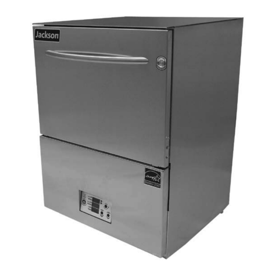
- Page 7 NOMENCLATURE AVENGER HT-E Undercounter dishmachine; high-temperature, hot-water sanitizing, with a booster tank and detergent and rinse-aid chemical feeder pumps. The manufacturer provides technical support for all of the dishmachines detailed in this manual. We strongly recommend that you refer to this manual before making a call to our technical support staff.
-
Page 8: Table Of Contents
TABLE OF CONTENTS SPECIFICATIONS Machine Dimensions ........................1 Operating Parameters ........................ 2 Electrical Requirements ......................3 INSTRUCTIONS Installation ..........................4 Chemical Feeder Pump Programming ..................8 Detergent Control ........................9 Operating ..........................10 MAINTENANCE Preventative Maintenance ......................14 Deliming ........................... 14 Troubleshooting ........................ -
Page 9: Specifications
MACHINE DIMENSIONS SPECIFICATIONS LEGEND: A- Water Inlet - 3/4" Male Garden Hose Thread (M-GHT) (Connect to a true 1/2" ID water line) *Note: Water inlet dimensions for units supplied with a PRV will be *8 1/8, **10 1/2 B- Electrical Connection C- Drain Connection - 6' coiled drain hose. -
Page 10: Operating Parameters
OPERATING PARAMETERS SPECIFICATIONS AVENGER HT-E Operating Capacity: Racks per Hour Dishes per Hour Glasses per Hour Tank Capacity (Gallons): Wash Tank Rinse Tank 2.12 Electrical Loads (as applicable): Wash Motor HP 0.75 Wash Heater KW Rinse Heater KW NOTICE NOTE: Always refer to the machine data plate for specific electrical and water requirements. -
Page 11: Electrical Requirements
ELECTRICAL REQUIREMENTS SPECIFICATIONS AVENGER HT-E NOTICE Electrical Characteristics All electrical ratings provided in this manual are for reference VOLTS only. Always refer to the machine data plate to get exact electrical information for this machine. All electrical work performed on... -
Page 12: Instructions
INSTRUCTIONS INSTALLATION VISUAL INSPECTION Before installing the unit, check packaging and machine for damage. Damaged packaging might be an indication of damage to the machine. If there is any type of damage to both packaging and unit, do not throw away the packaging. The Do not throw away dishmachine has been inspected at the factory before shipping and is expected to container if damage is... - Page 13 INSTRUCTIONS INSTALLATION WATER SUPPLY If water hardness tests at greater than 5 GPG, install the HTS-11 into the water line (1/2” ID pipe size minimum) before the dishmachine’s incoming water connection CONNECTIONS: point using copper pipe. Observe proper inlet/outlet water directions. Flow directions WATER HARDNESS are molded into the top of the head.
- Page 14 INSTRUCTIONS INSTALLATION ELECTRICAL POWER Electrical and grounding conductors must comply with the applicable portions of the National Electric Code ANSI/NFPA 70 (latest edition) and/or other electrical codes. CONNECTIONS The data plate is located at the left front side of the dishmachine. Refer to the data plate for machine operating requirements, machine voltage, total amperage, and serial number.
- Page 15 INSTRUCTIONS INSTALLATION CHEMICAL FEEDER This equipment is not recommended for use with deionized water or other aggressive fluids. Use of deionized water or other aggressive fluids will result in corrosion and failure of EQUIPMENT materials/components and will void the manufacturer's warranty. WARNING: Chlorine- The bottom of the chemical container cannot be located any higher than 8”...
-
Page 16: Chemical Feeder Pump Programming
INSTRUCTIONS INSTALLATION CHEMICAL The chemical feeder pump timers are located on screens 3, 4, and 5. To access the programming mode follow the process detailed below. FEEDER PUMP PROGRAMMING (INSTALLATION Millenium 3 Crouzet 1. Press “A” to cycle TECHNICIAN ONLY) through screens until Fill CYCLE TIMERS: reaching the "Fill Cycle... -
Page 17: Detergent Control
INSTRUCTIONS INSTALLATION DETERGENT Detergent usage and water hardness are two factors that contribute greatly to how efficiently this dishmachine will operate. Using detergent in the proper amount can CONTROL become a source of substantial savings. A qualified water treatment specialist can determine what is needed for maximum efficiency from the detergent. -
Page 18: Operating
OPERATING INSTRUCTIONS OPERATION PREPARATION Before operating the unit, verify the following: 1. Strainers are in place and clean. 2. Wash and rinse arms are screwed securely into place and end-caps are tight. 3. Wash and rinse arms rotate freely. 4. Chemical levels are correct. POWER UP To energize the unit, turn on the power at the service breaker. - Page 19 OPERATING INSTRUCTIONS OPERATION WARE Proper ware preparation will help ensure good results and fewer re-washes. If not done properly, ware might not come out clean and the efficiency of the dishmachine PREPARATION will be reduced. Putting unscrapped dishes into the machine affects its performance, so scraps should always be removed from ware before being loaded into a rack.
- Page 20 OPERATING INSTRUCTIONS OPERATION Based on use, the strainers might become clogged with soil and debris as the OPERATIONAL workday progresses. Operators should regularly inspect the strainers to ensure they have not become clogged. Clogged strainers will reduce the washing capability of INSPECTION the machine.
- Page 21 OPERATING INSTRUCTIONS OPERATION SHUTDOWN AND 6. Verify the nozzles and arms are free from obstruction. If clogged, remove end- caps, clean nozzles with a brush, and flush with fresh water. CLEANING 7. Replace end-caps and ensure they have been tightened. 8.
-
Page 22: Maintenance
PREVENTATIVE MAINTENANCE MAINTENANCE PREVENTATIVE The manufacturer of this dishmachine highly recommends that any maintenance and repairs not specifically discussed in this manual should be performed by qualified service MAINTENANCE personnel only. Performing maintenance on the dishmachine may void a warranty. By following the operating and cleaning instructions in this manual, users should get the most efficient results from the dishmachine. -
Page 23: Troubleshooting
TROUBLESHOOTING MAINTENANCE WARNING: Inspection, testing, and repair of electrical equipment should only be performed by qualified service personnel. Certain procedures in this section require electrical tests or measurements while power is applied to the machine. Exercise extreme caution at all times. If test points are not easily WARNING accessible, disconnect power, attach test equipment, and reapply power to test. - Page 24 TROUBLESHOOTING MAINTENANCE WARNING: Inspection, testing, and repair of electrical equipment should only be performed by qualified service personnel. Certain procedures in this section require electrical tests or measurements while power is applied to the machine. Exercise extreme caution at all times. If test points are not easily WARNING accessible, disconnect power, attach test equipment, and reapply power to test.
- Page 25 TROUBLESHOOTING MAINTENANCE AVENGER WASH HT-E DISPLAY TEMPERATURE TEMERATURA DEL LAVADO RINSE TEMPERATURE TEMPERATURA DE ACLARADO RINSE PRESSURE ENJUAGUE PRESIÓN FLUSH CYCLE The "Flush" light will activate after the unit has completed a predetermined number of cycles. When this light activates it is recommended that the user complete a flush cycle as detailed in the steps below.
-
Page 26: Plc Troubleshooting
PLC TROUBLESHOOTING MAINTENANCE SCREEN 1: The Avenger HT-E comes equipped with a PLC programmed to make troubleshooting and diagnostics more user-friendly. The following pages detail each screen associated HOME with the Avenger HT-E PLC display. Millenium 3 Crouzet STATUS: POWER ON... - Page 27 PLC TROUBLESHOOTING MAINTENANCE SCREEN 2: The “Faults” screen will be displayed when the operator has pressed “A” or “B” to cycle through screens and is intended to show the technician any faults that have occurred. FAULTS Millenium 3 Crouzet FAULTS: Line C will show any fault observed from previous cycles.
- Page 28 PLC TROUBLESHOOTING MAINTENANCE SCREEN 3: The “Fill Cycle Timers” screen allows the user to edit the fill, detergent, and rinse-aid timers for the initial fill cycle. FILL CYCLE TIMERS Millenium 3 Crouzet Fill CYCLE TIMERS: Fill Timer: Det Timer: 0010.0 R/A Timer: 0012.0s 1.
- Page 29 PLC TROUBLESHOOTING MAINTENANCE SCREEN 4: Screen 4 is the first “Wash Cycle Timers” screen and allows the user to edit the wash, rinse, and drain timers for the initial wash cycle. WASH CYCLE TIMERS 1 Millenium 3 Crouzet WASH CYCLE TIMERS: Wash Time: 00075s Rinse Time:...
- Page 30 PLC TROUBLESHOOTING MAINTENANCE SCREEN 5: Screen 5 is the second "Wash Cycle Timers" screen and allows the user to edit the detergent and rinse-aid timers for the initial wash cycle. WASH CYCLE TIMERS 2 Millenium 3 Crouzet WASH CYCLE TIMERS: Det Timer: 0005.0 R/A Timer:...
- Page 31 PLC TROUBLESHOOTING MAINTENANCE SCREEN 6: Screen 6 is the "Temperature Setpoints" screen and allows the user to edit the wash tank, top rinse tank, and bottom rinse tank temperatures. TEMPERATURE SETPOINTS Millenium 3 Crouzet TEMP SETPOINTS: WASH: 00155F RINSE: 00180F 1.
- Page 32 PLC TROUBLESHOOTING MAINTENANCE SCREEN 7: The "SaniSure Select" screen allows the user to turn SaniSure™ on or off. SaniSure™ ensures the rinse temperatures are high enough to achieve sanitization. SANISURE SELECT Millenium 3 Crouzet SANISURE SELECT: 0=OOF 1=ON 1. Line B shows the off option. •...
- Page 33 PLC TROUBLESHOOTING MAINTENANCE SCREEN 8: The "Rinse Tank Temperatures" screen allows the user to see the temperature readings in the top and bottom rinse tanks. RINSE TANK TEMPERATURES Millenium 3 Crouzet RINSE TANK TEMPS: TOP: 00187F BOTTOM: 00178F 1. Line C shows the current temperature reading of the top booster tank. 2.
- Page 34 PLC TROUBLESHOOTING MAINTENANCE SCREEN 10: The temperature select screen allows the user to select how temperatures are read, either in Celsius or Fahrenheit. TEMPERATURE SELECT Millenium 3 Crouzet FAHRENHEIT/CELUIS SELECTl 0=CELSIUS 1=FAHRENHEIT 1. Line C shows the Celsius option. • Press + or - to highlight line C. •...
- Page 35 PLC TROUBLESHOOTING MAINTENANCE SCREEN 12: Screen 13 shows the wash, rinse injector, pressure and temperature readings. WASH, Millenium 3 Crouzet RINSE INJECTOR, PRESSURE AND 00154 TEMPERATURE 00179 READINGS 00011 00001 1. Line A shows a reading of the wash RTD. 2.
-
Page 36: Parts
DATE R.M.I. NO: PART TO BE FREE FROM ALL BURRS AND SHARP EDGES THIS PRINT IS THE PROPERTY OF JACKSON WWS,INC. AND IS SUBJECT TO RECALL AND DO NOT SCALE DRAWING RETURN ON DEMAND. ANY USE, DISCLOSURE, REPRODUCTION, DUPLICATION, TRACING,... -
Page 37: Terminal Block Box Assembly
TERMINAL BLOCK BOX ASSEMBLY PARTS ITEM DESCRIPTION PART NUMBER Power Connection Decal 09905-011-47-35 Terminal Block Box 05700-003-27-69 Terminal Box Cover (not shown) 05700-003-27-70 Strain Relief 05975-003-37-56 Terminal Block Track 05700-000-43-60 Terminal Block 05940-500-02-19 10-24 Lock Nut 05310-373-01-00 Copper Conductors Decal 09905-011-62-72 Ground Lug 05940-200-76-00... -
Page 38: Control Panel
CONTROL PANEL PARTS 07610-004-04-18-R... - Page 39 CONTROL PANEL PARTS ITEM DESCRIPTION PART NUMBER Wash Heater, 4 kW 04540-003-99-44 **480 V Heater 04540-004-12-29 Heater Gasket 05330-011-61-34 **480 V Heater Gasket 05330-004-13-19 Rinse Booster (see Rinse Tank Assembly) 05700-004-01-15 Chemical Pump w/Squeeze Tube 04320-004-10-39 Control Box 05700-004-11-31 Vertical Float Switch 05930-011-48-98 Horizontal Float Switch 06680-004-05-50...
-
Page 40: Control Kick Panel
CONTROL KICK PANEL PARTS NOTE: DIELECTRIC COVER HIDDEN FOR CLARITY FRONT Control Panel Complete Assembly 05700-004-05-62 BACK NOTE: DIELECTRIC COVER HIDDEN FOR CLARITY ITEM DESCRIPTION PART NUMBER Lock Nut 10-24 S/S Hex w/ Nylon Insert 05310-373-01-00 Dielectric Cover 05700-004-06-12 PLC Controller 05700-004-17-68 Din Rail 05700-021-94-96... -
Page 41: Control Panel Display
RELEASED TO PRODUCTION REVISI R.M.I. NO: PART TO BE FREE FROM ALL BURRS AND SHARP EDGES THIS PRINT IS THE PROPERTY OF JACKSON WWS,INC. AND IS SUBJECT TO RE DO NOT SCALE DRAWING RETURN ON DEMAND. ANY USE, DISCLOSURE, REPRODUCTION, DUPLICATIO TOLERANCES... -
Page 42: 208/230 V Control Box
208/230 V CONTROL BOX PARTS BLUE/WHT VIO/WHT ORG/WHT WHT/RED 07610-004-04-18-R... - Page 43 208/230 V CONTROL BOX PARTS ITEM DESCRIPTION PART NUMBER Control Box 05700-004-11-32 Power Supply, 100-240 VAC, 12 VDC, 1.2 A, 15 Watt 05950-004-11-16 Peri-pump, 36 RPM, 24 VDC 04320-004-09-56 Terminal Board 05940-021-94-85 Relay 05945-004-10-48 Control Box Cover 05700-004-11-39 Plug, 2.6" Louvered 05975-003-77-39 Din Rail, 3"...
-
Page 44: 480 V Control Box
RETURN ON DEMAND. ANY USE, DISC Transformer 150 VA, 50/80 Hz 05950-011-50-70 TOLERANCES OR USE OF INFORMATION CONTAINED GAUGE: USED ON: INTEREST OF JACKSON WWS,INC. IS F AVENGER HT-E UNLESS OTHERWISE SPECIFIED NEXT ASSM: MATERIAL: APPROVED BY: CHECKED BY: 05700-004-11-40 DIMENSIONS IN INCHES ... -
Page 45: Chemical Feeder Pump Assembly
CHEMICAL FEEDER PUMP ASSEMBLY PARTS ITEM DESCRIPTION PART NUMBER Chemical Pump w/Squeeze Tube 04320-004-10-39 Chemical Pump Complete Assembly w/Motor 04320-004-09-56 07610-004-04-18-R... -
Page 46: Door Assembly
DOOR ASSEMBLY PARTS Door Reed Switch Enlarged 07610-004-04-18-R... - Page 47 DOOR ASSEMBLY PARTS ITEM DESCRIPTION PART NUMBER Flush Mount Plug 05975-004-04-36 10-32 x 1/2” Phillips Pan Head Screw 05305-173-12-00 Door Channel Seal 05700-003-55-49 Left and Right Door Gasket 05330-003-58-36 Top Door Gasket 05330-003-58-35 Inner Door 05700-003-33-21 Start Button 05930-004-04-22 Door Handle 05700-003-26-62 1/4-20 x 3/8”...
-
Page 48: Wash & Drain Motor Assembly
WASH & DRAIN MOTOR ASSEMBLY PARTS 07610-004-04-18-R... - Page 49 WASH & DRAIN MOTOR ASSEMBLY PARTS ITEM DESCRIPTION PART NUMBER Sump 05700-004-02-94 Sump Strainer 05700-004-03-73 Stand Pipe 05700-004-04-40 Manifold Gasket 05330-002-34-77 Wash Arm Assembly 05700-021-39-23 Wash Arm End-cap 05700-011-35-92 Wash Halo 05700-004-03-22 Locknut, 1/4-20 Hex w/Nylon Insert 05310-374-01-00 Wash Manifold 05700-004-08-96 Pump Assembly w/Mounting Bracket and Hoses 05700-004-04-04...
-
Page 50: Wash Arm Assembly
WASH ARM ASSEMBLY PARTS ITEM DESCRIPTION PART NUMBER Complete Wash Arm Assembly 05700-021-39-23 Wash Arm 05700-021-46-58 Bearing, Assembly 05700-021-35-97 O-Ring 05330-002-60-69 Wash Arm End-cap 05700-011-35-92 07610-004-04-18-R... -
Page 51: Rinse Manifold Assembly
RINSE MANIFOLD ASSEMBLY PARTS *Only present on the upper rinse hub. RINSE ARM BEARING KIT 06401-004-34-89 ITEM DESCRIPTION PART NUMBER Complete Rinse Arm Assembly 05700-004-01-56 Rinse Arm 05700-004-05-23 Nozzle 04730-004-01-07 Washer, Rinse Arm 05330-011-42-10 Bearing, Rinse Arm 03120-004-12-13 Bushing, Rinse Head 05700-021-33-84 O-ring, Silicon 05330-002-60-69... -
Page 52: Plumbing Assembly
PLUMBING ASSEMBLY PARTS Complete Rinse Injector Assembly 05700-004-08-29 With optional PRV An extra nipple (item #3) is required if the PRV is used. 07610-004-04-18-R... - Page 53 PLUMBING ASSEMBLY PARTS ITEM DESCRIPTION PART NUMBER Valve, 1/2" 04810-003-71-56 Union, 1/2" x 1/2" Brass 04730-003-62-44 Nipple, 1/2" Close Brass 04730-207-15-00 Nipple, 1/2" x 4" NPT Brass 04730-207-04-00 Adapter, 1/2" Fitting, Male 04730-011-59-53 Elbow, 1/2" S. CU to FTG 04730-406-31-01 Hose Adapter 04720-004-24-68 PRV, 1/2"...
-
Page 54: Rinse Tank Assembly
RINSE TANK ASSEMBLY PARTS 07610-004-04-18-R... - Page 55 RINSE TANK ASSEMBLY PARTS ITEM DESCRIPTION PART NUMBER Booster Heater, 2 kW 04540-003-98-38 ** 480 V Unit Booster Heater 04540-004-13-30 Heater Gasket 05330-011-61-34 ** 480 V Heater Gasket 05330-011-47-79 Lockwasher, Split 5/16" S/S 05311-275-01-00 Nut, Hex 5/16"-18 S/S 05310-275-01-00 Booster 05700-004-04-16 ** 480 V Booster 05700-004-13-25...
-
Page 56: Wash Pump Assembly
WASH PUMP ASSEMBLY PARTS 07610-004-04-18-R... - Page 57 WASH PUMP ASSEMBLY PARTS ITEM DESCRIPTION PART NUMBER Hose 1 1/4" x 8" 05700-004-08-21 Sump 05700-004-02-94 Clamp, 1 1/16" to 2" 04730-719-18-00 Drain Pump 04730-003-91-41 Elbow, Hose Barb Drain 04720-004-20-12 Drain Hose, 8" 04720-111-39-73 Drain Hose, 3" 04720-111-39-73 Clamp, 13/16" to 1 1/2" 04730-719-06-09 Wash Pump 06105-004-24-79...
-
Page 58: Schematics
208/230 V, 50/60 HZ, 1-PHASE SCHEMATICS GROUND POWER SWITCH POWER SUPPLY WASH MOTOR CONTACTOR WASH HEATER DOOR SAFETY SWITCH RTD1 WASH REGULATING THRMOSTAT LED 1 FLUSH INDICATOR LED RINSE HEATER TOP CYCLE SWITCH LED 2 DELIME INDICATOR LED RTD2 TOP RINSE TANK THERMOSTAT RTD3 LOWER RINSE TANK THERMOSTAT RINSE HEATER BOTTOM... -
Page 59: 480 V, 60 Hz, 3-Phase
480 V, 60 HZ, 3-PHASE SCHEMATICS 07610-004-04-18-R... - Page 60 Jackson WWS, Inc. • 6209 N. US Hwy 25E • Gray, KY 40734 USA 1.888.800.5672 • www.jacksonwws.com Avenger HT-E Manual • Rev R • 07610-004-04-18 • Issued: 01-01-14 • Revised: 10-05-16 ®...
Need help?
Do you have a question about the AVENGER HT-E and is the answer not in the manual?
Questions and answers