Table of Contents
Advertisement
Quick Links
PN 3952319
November 2010
© 2010 Fluke Corporation. All rights reserved. Printed in USA. Specifications are subject to change without notice.
All product names are trademarks of their respective companies.
1.888.610.7664
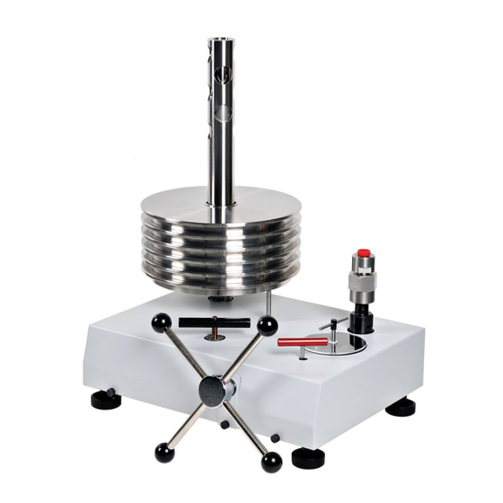
P3800 Series
High Pressure Hydraulic Deadweight Tester
www.calcert.com
15
10
20
5
25
0
30
Users Manual
sales@calcert.com
Advertisement
Table of Contents

Related Manuals for Fluke P3800C


Summary of Contents for Fluke P3800C
- Page 1 High Pressure Hydraulic Deadweight Tester Users Manual PN 3952319 November 2010 © 2010 Fluke Corporation. All rights reserved. Printed in USA. Specifications are subject to change without notice. All product names are trademarks of their respective companies. 1.888.610.7664 www.calcert.com sales@calcert.com...
- Page 2 Fluke authorized resellers shall extend this warranty on new and unused products to end-user customers only but have no authority to extend a greater or different warranty on behalf of Fluke. Warranty support is available only if product is purchased through a Fluke authorized sales outlet or Buyer has paid the applicable international price.
-
Page 3: Table Of Contents
Table of Contents Chapter Title Page 1 General Information ................1-1 Introduction......................1-1 How to Contact Fluke ..................1-1 Safety Information ..................... 1-2 Symbols Used in this Manual ................1-2 Hydraulic Circuit Schematic................1-3 2 Preparation ..................2-1 Location ......................2-1 Fluid Filling ....................... - Page 4 List of Tables Table Title Page 1-1. Symbols........................1-2 1.888.610.7664 www.calcert.com sales@calcert.com...
- Page 5 List of Figures Figure Title Page 1-1. Hydraulic Circuit Schematic .................. 1-3 3-1. Pressure Connection - Method 1 ................3-1 3-2. Pressure Connection - Method 2 ................3-2 3-3. Remove Trapped Air....................3-2 3-4. Turn Capstan Fully Clockwise................3-3 3-5. Prime the Pressure Intensifier ................
-
Page 6: General Information
This manual contains operation and routine and preventive maintenance instructions for the Model P3830, P3840, and P3860 High Pressure Hydraulic Deadweight Tester (DWT) manufactured by Fluke. This section of the manual provides general information about the DWT. The P3800 Series of Deadweight Testers (DWT) provides a convenient means of testing high pressure instruments for calibration accuracy. -
Page 7: Safety Information
Symbols used on the Deadweight Tester (DWT) and in this manual are explained in Table 1-1. Table 1-1. Symbols Symbol Description Earth Ground Important Information: refer to manual Do not dispose of this product as unsorted municipal waste. Go to Fluke’s website for recycling information. 1.888.610.7664 www.calcert.com sales@calcert.com... -
Page 8: Hydraulic Circuit Schematic
General Information Hydraulic Circuit Schematic Hydraulic Circuit Schematic glf01.eps Figure 1-1. Hydraulic Circuit Schematic 1.888.610.7664 www.calcert.com sales@calcert.com... -
Page 9: Preparation
Chapter 2 Preparation Location Note Item number references in the following text, (1), (2), etc, relate to the hydraulic system schematic, shown in the figures below. Place the unit onto a clean, flat surface of a strong and rigid workbench. Ensure that the front of the unit is approximately ¾”... -
Page 10: Operation
Chapter 3 Operation Connections Connect the EUT to the test station using a gauge adapter and lens ring from the selection provided. W Caution This unit can generate very high pressures and, as a consequence, only metal-to-metal sealing is acceptable, i.e. no sealing washers of any description should be used (see Figure 3.1 and 3.2 for methods of sealing). -
Page 11: Procedure For Removing Trapped Air From System
P3800 Series Users Manual glf03.eps Figure 3-2. Pressure Connection - Method 2 Procedure for Removing Trapped Air from System glf04.bmp Figure 3-3. Remove Trapped Air 1.888.610.7664 www.calcert.com sales@calcert.com... -
Page 12: Turn Capstan Fully Clockwise
Operation Procedure for Removing Trapped Air from System 1. Open HP valve (1) and LP valve (2) fully, (counter-clockwise). 2. Open reservoir valve (3), (approximately 4 turns counter-clockwise). 3. Turn capstan fully out (counter-clockwise), and wait for approximately 60 seconds. glf05.bmp Figure 3-4. -
Page 13: Procedure For Priming The Pressure Intensifier
P3800 Series Users Manual Procedure for Priming the Pressure Intensifier glf06.bmp Figure 3-5. Prime the Pressure Intensifier 1. Close LP valve (2) by turning fully clockwise. 2. Turn capstan in (clockwise) until resistance is felt. This is a result of the pressure required to move the intensifier piston backward in its cylinder, and to lift the measuring piston and weight carrier. -
Page 14: Procedure For Generating System Pressure
Operation Procedure for Generating System Pressure Procedure for Generating System Pressure TEST PORT INTENSIFIER RESERVOIR VALVE (3) HP VALVE (1) LP VALVE (2) CAPSTAN glf07.eps Figure 3-6. Generate System Pressure 1. Close HP valve (1). 2. Open LP valve (2). 3. -
Page 15: Generating Calibration Pressure
P3800 Series Users Manual glf08.bmp Figure 3-7. Close Reserve Valve 4. Close reservoir valve (3). 5. Turn capstan in to generate system pressure. The displaced fluid from the ram screw moves the intensifier piston, generating system pressure to lift the measuring piston and weights. -
Page 16: Correct Float Position
Operation Generating Calibration Pressure W Caution When reducing pressure ALWAYS use the capstan (by winding out counter-clockwise). NEVER use any of the valves. When reducing from high system pressures, some pressure is still retained in the system, even after winding the capstan fully out (approximately 700 psi / 50 bar). -
Page 17: Maintenance
Chapter 4 Maintenance Introduction The P3800 Series of High Pressure Deadweight Testers have been designed to require minimal maintenance. Routine maintenance entails keeping the unit clean and free from excess oil. The operating fluid should be changed at regular intervals due to potential contamination from items under test. -
Page 18: Cleaning
P3800 Series Users Manual PISTON NUT B PISTON PISTON NUT A CYLINDER O RING PISTON COLUMN glf10.eps Figure 4-1. Piston/Cylinder Removal Cleaning 1. Use “non-fluffing”, non-abrasive, lint-free tissue or absorbent cloth. Hold the Piston by the larger “head” end, and rub the tissue back and forth along its length. 2. -
Page 19: Replacement
Maintenance Replacement W Caution Never touch the working surface of a clean piston with bare fingers — the natural oil in your skin can cause the piston and cylinder to stick. 5. Wipe excess fluid from the outside surfaces of the cylinder. 6. -
Page 20: Recalibration
Chapter 5 Recalibration Introduction To maintain the highest accuracy the DWT should be recalibrated at regular intervals. The exact period between recalibrations is dependant on ambient conditions and use. As a general guide, recalibration period should be more than 1 year and less than 3 years. Do's and Don'ts Don'ts •... -
Page 21: Pressure Corrections
Chapter 6 Pressure Corrections Introduction Pressure correction is required for high accuracy work and is due to the effects of pressure on the PCU assembly during operation. By reference to the certificate of calibration provided the actual pressure in the system can be obtained. All values relate to the environmental conditions stated on the certificate. - Page 22 P3800 Series Users Manual Temperature and Gravity Corrections Deadweight testers are manufactured to give an accurate pressure reference at the specified temperature and gravity values indicated on the certificates. The following Standard Values are applied during calibration unless otherwise requested during manufacture (see Certificate).
-
Page 23: Nomogram For Finding The Value Of
Pressure Corrections Temperature and Gravity Corrections Explanation of Nomogram A straight line passing through the known values of altitude (H) and latitude (L) of the site of the DWT, when extended to scale ‘g’, will indicate the approximate value of ‘g’. 9.83 16000 14000...
Need help?
Do you have a question about the P3800C and is the answer not in the manual?
Questions and answers