
Related Manuals for Hoshizaki DCM-500B H


Summary of Contents for Hoshizaki DCM-500B H
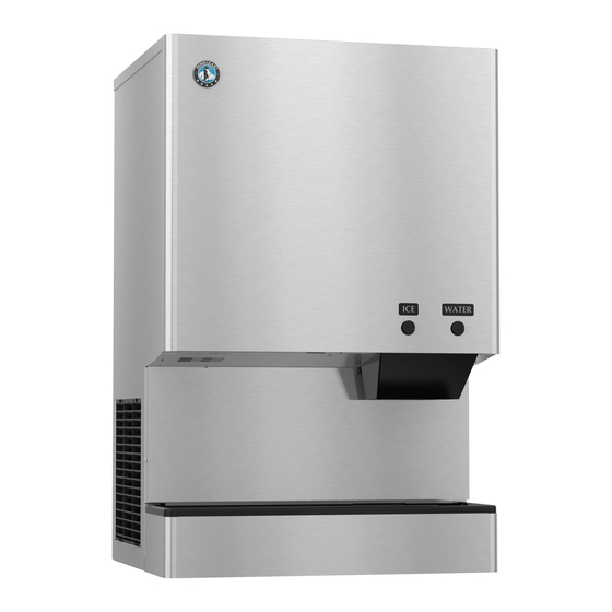
- Page 1 Instruction Manual Cubelet Icemaker/Dispenser Models DCM-300BAH(-OS) DCM-500B_H(-OS) DCM-751BWH(-OS) DCM-752BAH(-OS) Issued: 3-25-2020 hoshizakiamerica.com...
- Page 2 Should the reader have any questions or concerns which have not been satisfactorily addressed, please call, send an e-mail message, or write to the Hoshizaki Technical Support Department for assistance. Phone: 1-800-233-1940; (770) 487-2331 Fax: 1-800-843-1056;...
-
Page 3: Table Of Contents
IMPORTANT This manual should be read carefully before the appliance is installed and operated. Read the warnings and guidelines contained in this manual carefully as they provide essential information for the continued safe use and maintenance of the appliance. Retain this manual for any further reference that may be necessary. CONTENTS Important Safety Information .................... -
Page 4: Important Safety Information
Important Safety Information Throughout this manual, notices appear to bring your attention to situations which could result in death, serious injury, damage to the appliance, or damage to property. WARNING Indicates a hazardous situation which could result in death or serious injury. - Page 5 WARNING, continued • The appliance is not intended for use by persons (including children) with reduced physical, sensory, or mental capabilities, or lack of experience and knowledge, unless they have been given supervision or instruction concerning use of the appliance by a person responsible for their safety. •...
-
Page 6: Specifications
I. Specifications A. Electrical and Refrigerant Data The rating label and nameplate provide electrical and refrigerant data. The rating label can be seen by removing the front panel. The nameplate is located on the rear panel. For certification marks, see the nameplate. We reserve the right to make changes in specifications and design without prior notice. -
Page 7: Dcm-751Bwh(-Os)
3. DCM-751BWH(-OS) Single Phase DCM-751BWH(-OS) Model Number AC Supply Voltage 115-120/60/1 Compressor 115V 14.6RLA 77LRA Gear Motor 120V 3.0FLA 1/4HP Fan Motor - - - Agitating Motor 120V 1.8FLA(TOTAL) 110W Dispensing Motor 120V 0.9FLA 55W Other 120V 0.6A Maximum Fuse Size 20 AMPS Max. -
Page 8: Dimensions/Connections
B. Dimensions/Connections 1. Air-Cooled Models (DCM-300BAH(-OS), DCM-500BAH(-OS)) Unit: mm [in.] Front Rear Side DCM-500BAH(-OS) DCM-500BAH(-OS) DCM-500BAH(-OS) DCM-300BAH(-OS) DCM-300BAH(-OS) DCM-300BAH(-OS) DCM-300BAH DCM-300BAH-OS NOTICE DCM-500BAH DCM-500BAH-OS Allow 6" (15 cm) clearance at rear and A 100 [3.94] sides for proper air circulation and ease B 93 [3.66] C NA 100 [3.94]... -
Page 9: Air-Cooled Models (Dcm-752Bah(-Os))
2. Air-Cooled Models (DCM-752BAH(-OS)) Unit: mm [in.] Front Side Rear NOTICE DCM-752BAH DCM-752BAH-OS A 100 [3.94] Allow 6" (15 cm) clearance at rear and B 165 [6.5] sides for proper air circulation and ease C NA 100 [3.94] of maintenance and/or service should D NA 165 [6.5] they be required. -
Page 10: Water-Cooled Models (Dcm-500Bwh(-Os))
3. Water-Cooled Models (DCM-500BWH(-OS)) Unit: mm [in.] Front Side Rear NOTICE DCM-500BWH DCM-500BWH-OS A 100 [3.94] Allow 6" (15 cm) clearance at rear and B 93 [3.66] sides for proper air circulation and ease C NA 100 [3.94] of maintenance and/or service should D NA 99 [3.90] they be required. -
Page 11: Water-Cooled Models (Dcm-751Bwh(-Os))
4. Water-Cooled Models (DCM-751BWH(-OS)) Unit: mm [in.] Front Rear Side NOTICE DCM-751BWH DCM-751BWH-OS A 100 [3.94] Allow 6" (15 cm) clearance at rear and B 165 [6.5] sides for proper air circulation and ease C NA 100 [3.94] of maintenance and/or service should D NA 165 [6.5] they be required. -
Page 12: Installation And Operating Instructions
II. Installation and Operating Instructions WARNING • The appliance must be installed in accordance with applicable national, state, and local codes and regulations. • Failure to install, operate, and maintain the appliance in accordance with this manual will adversely affect safety, performance, component life, and warranty coverage and may result in costly water damage. -
Page 13: Checks Before Installation
• Check that the refrigerant lines do not rub or touch lines or other surfaces, and that the fan blade (if applicable) turns freely. • This appliance can be installed on a countertop or on an optional stand. If using an optional stand, see the table below. For further options, contact your local Hoshizaki distributor. Model Number... -
Page 14: How To Remove Panels
C. How to Remove Panels See Fig. 1 • Front Panel: Remove the screw. Lift up and towards you. Disconnect the connector on push-button models. • Top Panel: Lift up at front slightly, push rearward and lift off. • Apron Panel: Remove the screws and pull towards you. Disconnect the connectors on optical-sensor models. -
Page 15: Setup
D. Setup 1) Position the appliance in the selected permanent location. If applicable, attach optional 6" legs or attach to an optional stand. If attaching to a stand, refer to the instructions included with the stand. If removing the drip tray, refer to the instructions included with the HS kit (HS-5003 for DCM-751BWH and DCM-752BAH or HS-5002 for DCM-751BWH-OS and DCM-752BAH-OS). -
Page 16: Water Supply And Drain Connections
• External filters, strainers, or softeners may be required depending on water quality. Contact your local Hoshizaki Certified Service Representative or local Hoshizaki distributor for recommendations. • A plumbing permit and services of a licensed plumber may be required in some areas. -
Page 17: Icemaker
1. Icemaker • Icemaker water supply inlet is 1/2" female pipe thread (FPT). A minimum of 1/4" nominal ID copper water tubing or equivalent is required for the icemaker water supply line. • An icemaker water supply line shut-off valve and drain valve should be installed. •... -
Page 18: Water-Cooled Condenser
2. Water-Cooled Condenser a) Connection to an Open Drain System • Condenser water supply inlet is 1/2" female pipe thread (FPT). A minimum of 1/4" nominal ID copper water tubing or equivalent is required for the condenser water supply line. •... - Page 19 b) Connection to a Closed Loop System • Condenser water supply inlet is 1/2" female pipe thread (FPT). A minimum of 1/4" nominal ID copper water tubing or equivalent is required for the condenser water supply line. • Condenser return outlet is 3/8" FPT. A minimum of 1/4" nominal ID copper water tubing or equivalent is required for the condenser return line.
-
Page 20: Final Checklist
G. Final Checklist WARNING CHOKING HAZARD: Ensure all components, fasteners, and thumbscrews are securely in place after installation. Make sure that none have fallen into the ice storage bin. 1) Is the icemaker level? 2) Is the icemaker in a site where the ambient temperature is within 45°F to 100°F (7°C to 38°C) and the water temperature within 45°F to 90°F (7°C to 32°C) all year around? 3) Is there at least 6"... -
Page 21: Startup
H. Startup WARNING • All parts are factory-adjusted. Improper adjustments may adversely affect safety, performance, component life, and warranty coverage. • If the icemaker is turned off, wait for at least 3 minutes before restarting the icemaker to prevent damage to the compressor. •... - Page 22 10) Confirm bin control operation: Remove the control box cover and ice storage bin cover, move the control switch to the "ICE" position, then engage the safety switch on the front frame. See Fig. 7. After the "GM" LED on the control board turns on (5 sec.), the 5-min. ice purge timer starts.
-
Page 23: Dispense Mode Switch
I. Dispense Mode Switch The dispense mode switch has "CONTINUOUS" and "PORTION" positions. When the dispense mode switch is in the "CONTINUOUS" position, ice dispenses continuously for a maximum of 60 seconds per activation. When the dispense mode switch is in the "PORTION"... -
Page 24: Maintenance
III. Maintenance The appliance must be maintained in accordance with the instruction manual and labels provided. Consult with your local Hoshizaki Certified Service Representative about maintenance service. WARNING • Only qualified service technicians should service the appliance. • To reduce the risk of electric shock, do not touch the power switch or control switch with damp hands. -
Page 25: Maintenance Schedule
A. Maintenance Schedule The maintenance schedule below is a guideline. More frequent maintenance may be required depending on water quality, the appliance's environment, and local sanitation regulations. Maintenance Schedule Frequency Area Task Bi-Weekly Air Filters Inspect. Wash with warm water and neutral cleaner if dirty. Monthly External Water Check for proper pressure and change if necessary. -
Page 26: Cleaning And Sanitizing Instructions
1. Water System a) Cleaning Solution Dilute 9.6 fl. oz. (0.29 l) of Hoshizaki "Scale Away" with 1.6 gal. (6.0 l) of warm water. This is a minimum amount. Make more solution if necessary. IMPORTANT! For safety and maximum effectiveness, use the solution immediately after dilution. - Page 27 7) Replace spout A, spout B, and the ice storage bin cover in their correct positions. 8) Allow the icemaker to sit for 10 minutes before operation. If you placed a clamp on the reservoir hose in step 6, remove it before operation. 9) In bad or severe water conditions, clean the float switch assembly as described below.
- Page 28 Perform after cleaning and sanitizing the water system as outlined above. a) Cleaning Solution Dilute 9.6 fl. oz. (0.29 l) of Hoshizaki "Scale Away" with 1.6 gal. (6.0 l) of warm water. b) Sanitizing Solution Dilute 0.82 fl. oz. (25 ml) of a 5.25% sodium hypochlorite solution (chlorine bleach) with 1.6 gal.
- Page 29 3) Remove the ice storage bin cover. 4) Remove the motor bracket thumbscrews, first from the vertical plane and then from the horizontal plane. While holding on to the corresponding agitator or auger, move the agitating motor or the dispensing motor towards you. Remove the agitator(s) and the dispensing auger from the ice storage bin.
-
Page 30: Preparing The Appliance For Periods Of Non-Use
IV. Preparing the Appliance for Periods of Non-Use NOTICE When storing the appliance for an extended time or in sub-freezing temperatures, follow the instructions below to prevent damage. When the appliance is not used for two or three days under normal conditions, it is sufficient to move the power switch to the "OFF"... - Page 31 2. On water-cooled model only, remove the water from the water-cooled condenser: 1) Make sure the control switch and the power switch are in the "OFF" position and that the power supply is off. Remove the top, apron, and left side panels. 2) Close the condenser water supply line shut-off valve.
-
Page 32: Disposal
V. Disposal The appliance contains refrigerant and must be disposed of in accordance with applicable national, state, and local codes and regulations. Refrigerant must be recovered by properly certified service personnel. - Page 33 618 Hwy. 74 South, Peachtree City, GA 30269 USA (P) 770.487.2331 (F) 770.487.3360 hoshizakiamerica.com 1A6050-010...
Need help?
Do you have a question about the DCM-500B H and is the answer not in the manual?
Questions and answers