Hoshizaki DCM-751BAH Instruction Manual
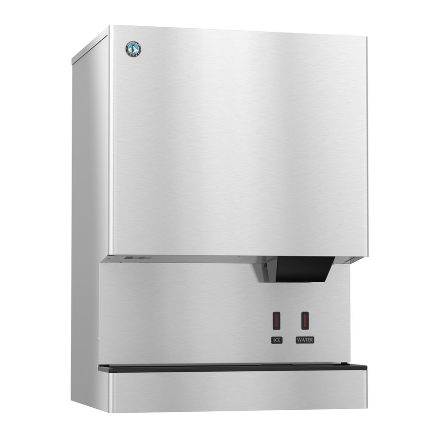
Cubelet icemaker/dispenser
Hide thumbs
Also See for DCM-751BAH:
- Service manual (61 pages) ,
- Dimensions and specifications (2 pages) ,
- Instruction manual (33 pages)
Table of Contents
Advertisement
Quick Links
Download this manual
See also:
Service Manual
Advertisement
Table of Contents

Subscribe to Our Youtube Channel
Related Manuals for Hoshizaki DCM-751BAH


Summary of Contents for Hoshizaki DCM-751BAH
- Page 1 Hoshizaki Hoshizaki America, Inc. Cubelet Icemaker/Dispenser Models DCM-751BAH(-OS) DCM-751BWH(-OS) INSTRUCTION MANUAL “A Superior Degree of Reliability” www.hoshizaki.com Issued: 3-23-2011...
- Page 2 Should the reader have any questions or concerns which have not been satisfactorily addressed, please call, write, or send an e-mail message to the Hoshizaki Technical Support Department for assistance. HOSHIZAKI AMERICA, INC.
-
Page 3: Table Of Contents
CONTENTS Important Safety Information ....................4 I. Specifications ........................5 A. Electrical Data ....................... 5 1. DCM-751BAH (air-cooled) ..................5 2. DCM-751BAH-OS (air-cooled)................. 6 3. DCM-751BWH (water-cooled) ................. 7 4. DCM-751BWH-OS (water-cooled) ................8 B. Dimensions/Connections ....................9 1. -
Page 4: Important Safety Information
Important Safety Information Throughout this manual, notices appear to bring your attention to situations which could result in death, serious injury, or damage to the unit. WARNING Indicates a hazardous situation which could result in death or serious injury. CAUTION Indicates a situation which could result in damage to the unit. -
Page 5: Specifications
I. Specifications A. Electrical Data 1. DCM-751BAH (air-cooled) HOSHIZAKI ICE MAKER MODEL NUMBER DCM-751BAH SERIAL NUMBER AC SUPPLY VOLTAGE 115-120/60/1 COMPRESSOR 115V 77LRA 14.6RLA GEAR MOTOR 120V 3.0FLA 1/4HP FAN MOTOR 120V 1.0FLA 50W AGITATING MOTOR 120V 1.8FLA(TOTAL) 110W DISPENSING MOTOR 120V 0.9FLA 55W... -
Page 6: Dcm-751Bah-Os (Air-Cooled)
2. DCM-751BAH-OS (air-cooled) HOSHIZAKI ICE MAKER MODEL NUMBER DCM-751BAH-OS SERIAL NUMBER AC SUPPLY VOLTAGE 115-120/60/1 COMPRESSOR 115V 77LRA 14.6RLA GEAR MOTOR 120V 3.0FLA 1/4 HP FAN MOTOR 120V 1.0FLA 50W AGITATING MOTOR 120V 1.8FLA(TOTAL) 110W DISPENSING MOTOR 120V 0.9FLA 55W OTHER 120V 0.6A... -
Page 7: Dcm-751Bwh (Water-Cooled)
3. DCM-751BWH (water-cooled) HOSHIZAKI ICE MAKER MODEL NUMBER DCM-751BWH SERIAL NUMBER AC SUPPLY VOLTAGE 115-120/60/1 COMPRESSOR 115V 77LRA 14.6RLA GEAR MOTOR 120V 3.0FLA 1/4HP FAN MOTOR ---- ---- ---- AGITATING MOTOR 120V 1.8FLA(TOTAL) 110W DISPENSING MOTOR 120V 0.9FLA 55W OTHER 120V 0.6A... -
Page 8: Dcm-751Bwh-Os (Water-Cooled)
4. DCM-751BWH-OS (water-cooled) HOSHIZAKI ICE MAKER MODEL NUMBER DCM-751BWH-OS SERIAL NUMBER AC SUPPLY VOLTAGE 115-120/60/1 COMPRESSOR 115V 77LRA 14.6RLA GEAR MOTOR 120V 3.0FLA 1/4HP FAN MOTOR ---- ---- ---- AGITATING MOTOR 120V 1.8FLA(TOTAL) 110W DISPENSING MOTOR 120V 0.9FLA 55W OTHER 120V 0.6A... -
Page 9: Dimensions/Connections
B. Dimensions/Connections 1. DCM-751BAH (air-cooled) -
Page 10: Dcm-751Bah-Os (Air-Cooled)
2. DCM-751BAH-OS (air-cooled) -
Page 11: Dcm-751Bwh (Water-Cooled)
3. DCM-751BWH (water-cooled) -
Page 12: Dcm-751Bwh-Os (Water-Cooled)
4. DCM-751BWH-OS (water-cooled) -
Page 13: Installation And Operating Instructions
• See the nameplate on the rear panel, and check that your voltage supplied corresponds with the voltage specified on the nameplate. • This icemaker can be installed on a countertop or on an optional stand. If using an optional stand, Hoshizaki Stand SD-700 or SD-750 is recommended. For further options, contact your local Hoshizaki distributor. • The drip tray on the front of the icemaker is removable for installations using an in-counter drain. Drip tray removal requires HS-5003 for DCM-751 B_H or HS-5002 for DCM-751B_H-OS. -
Page 14: How To Remove Panels
B. How to Remove Panels See Fig. 1 or Fig. 2 • Front Panel: Remove the screw. Lift up and towards you. Disconnect the connector on push-button models. • Top Panel: Lift up at front slightly, push rearward and lift off. • Apron Panel: Remove the screws and pull towards you. Disconnect the connectors on Opti-Serve models. • Side Panels: Remove the screws and pull towards you. DCM-751B_H DCM-751B_H-OS (Push-Button Models) (Opti-Serve Models) Top Panel Top Panel Side Panel Side Panel Side Panel Side Panel Front Panel Front Panel Connector Connectors Apron Panel... -
Page 15: Location
C. Location CAUTION 1. This icemaker is not intended for outdoor use. Normal operating ambient temperature should be within 45°F to 100°F (7°C to 38°C); Normal operating water temperature should be within 45°F to 90°F (7°C to 32°C). Operation of the icemaker, for extended periods, outside of these normal temperature ranges may affect icemaker performance. -
Page 16: Electrical Connection
E. Electrical Connection WARNING 1. Electrical connection must be hard-wired and must meet national, state, and local electrical code requirements. Failure to meet these code requirements could result in death, electric shock, serious injury, fire, or extensive damage to equipment. 2. -
Page 17: Water Supply And Drain Connections
10 PSIG. Do not run the icemaker until the proper water pressure is reached. • A plumbing permit and services of a licensed plumber may be required in some areas. • External filters, strainers, or softeners may be required depending on water quality. Contact your local Hoshizaki distributor for recommendations. • Water supply pressure should be a minimum of 10 PSIG and a maximum of 113 PSIG. If the pressure exceeds 113 PSIG, the use of a pressure reducing valve is required. • The storage bin drain line, drip tray drain line, and water-cooled condenser drain line (if applicable) must be run separately. -
Page 18: Icemaker
Drip Tray Drain Outlet Stand 3/4" FPT Vent Separate piping to approved Tube drain. Leave a 2-inch (5-cm) vertical air gap between the end of each pipe and the drain. Minimum 3/4" Nominal ID 2-inch (5-cm) Hard Pipe air gap Fig. 4 DCM-751BAH(-OS) Floor Drain... -
Page 19: Water-Cooled Condenser
2. Water-Cooled Condenser a) Connection to an Open Drain System • Condenser water supply inlet is 1/2" female pipe thread (FPT). A minimum of 1/4" nominal ID copper water tubing or equivalent is required for the condenser water supply line. • A condenser water supply line shut-off valve and drain valve should be installed. • Condenser drain outlet is 3/8" FPT. A minimum of 1/4" nominal ID hard pipe or equivalent is required for the condenser drain line. • In some areas, a back flow preventer may be required in the condenser water supply line. • In order to maintain the proper high side pressure, the condenser water supply inlet temperature should not drop below 45°F (7°C) and the condenser drain outlet temperature must be in the 104°F to 115°F (40°C to 46°C) range. -
Page 20: B) Connection To A Closed Loop System
b) Connection to a Closed Loop System • Condenser water supply inlet is 1/2" female pipe thread (FPT). A minimum of 1/4" nominal ID copper water tubing or equivalent is required for the condenser water supply line. • Condenser return outlet is 3/8" FPT. A minimum of 1/4" nominal ID copper water tubing or equivalent is required for the condenser return line. • Shut-off valves and drain valves should be installed at both the condenser water supply inlet and condenser return outlet. • The water supply to the condenser should not drop below 4 GPM. • The pressure differential between the condenser water supply inlet and condenser return outlet must be no less than 10 PSIG. • When using a glycol blend, the solution mixture should be less than 30% glycol. -
Page 21: Final Checklist
G. Final Checklist WARNING CHOKING HAZARD: Ensure all components, fasteners, and thumbscrews are securely in place after installation. Make sure that none have fallen into the storage bin. 1) Is the icemaker level? 2) Is the icemaker in a site where the ambient temperature is within 45°F to 100°F (7°C to 38°C) and the water temperature within 45°F to 90°F (7°C to 32°C) all year around? 3) Is there at least 6" (15 cm) clearance at rear and sides and 24" (61 cm) at top for proper air circulation and ease of maintenance and service? -
Page 22: Startup
H. Startup WARNING 1. All parts are factory-adjusted. Improper adjustments may adversely affect safety, performance, component life, and warranty coverage. 2. If the icemaker is turned off, wait for at least 3 minutes before restarting the icemaker to prevent damage to the compressor. 3. -
Page 23: Dispense Mode Switch
0.6 and 20 seconds. See Fig. 8. When shipped, the ice dispense time control is set to the minimum dispense time of 0.6 sec. At this setting, approximately 0.72 oz. of ice is dispensed. The DCM-751BAH(-OS) and DCM-751BWH(-OS) dispense approximately 1.2 oz. of ice per second. -
Page 24: Cleaning And Maintenance
Consult with your local distributor about cleaning and maintenance service. To obtain the name and phone number of your local distributor, visit www.hoshizaki.com or call Hoshizaki Technical Support at 1-800-233-1940 in the USA. -
Page 25: Cleaning And Sanitizing Instructions
A. Cleaning and Sanitizing Instructions Hoshizaki recommends cleaning and sanitizing this unit at least twice a year. More frequent cleaning and sanitizing, however, may be required in some existing water conditions. WARNING 1. To prevent injury to individuals and damage to the icemaker, do not use ammonia type cleaners. - Page 26 8) Allow the icemaker to sit for 10 minutes before operation. If you placed a clamp on the reservoir hose in step 6, remove it before operation. 9) In bad or severe water conditions, clean the float switch assembly as described below. Otherwise, continue to step 10.
-
Page 27: Dispensing Components
"ICE" position. Allow the icemaker to run for 30 minutes, then clean and sanitize the dispensing components as outlined below. 2. Dispensing Components Perform after cleaning and sanitizing the water system as outlined above. a) Cleaning Solution Dilute 9.6 fl. oz. (0.29 l) of Hoshizaki "Scale Away" with 1.6 gal. (6.0 l) of warm water. b) Sanitizing Solution Dilute 0.82 fl. oz. (25 ml) of a 5.25% sodium hypochlorite solution (chlorine bleach) with 1.6 gal. (6.0 l) of warm water. c) Cleaning and Sanitizing Procedure 1) Move the control switch to the "OFF" position, then turn off the power supply. - Page 28 4) Remove the motor bracket thumbscrews, first from the vertical plane and then from the horizontal plane. While holding on to the corresponding agitator or auger, move the agitating motor or the dispensing motor towards you. Remove the agitators and the dispensing auger from the storage bin.
-
Page 29: Maintenance
B. Maintenance The maintenance schedule below is a guideline. More frequent maintenance may be required depending on water quality, the icemaker's environment, and local sanitation regulations. WARNING 1. Only qualified service technicians should service this icemaker. 2. Move the control switch and the power switch to the "OFF" position and turn off the power supply before servicing. Lockout/Tagout to prevent the power supply from being turned back on inadvertently. -
Page 30: Preparing The Icemaker For Long Storage
C. Preparing the Icemaker for Long Storage CAUTION When storing the icemaker for an extended time or in sub-freezing temperatures, follow the instructions below to prevent damage. When the icemaker is not used for two or three days under normal conditions, it is sufficient to only move the control switch to the "OFF" position. When storing the icemaker for extended time or in sub-freezing temperatures, follow the instructions below. - Page 31 2. On water-cooled model only, remove the water from the water-cooled condenser: 1) Make sure the control switch and the power switch are in the "OFF" position and that the power supply is off. Remove the top, apron, and left side panels. 2) Close the condenser water supply line shut-off valve. If connected to a closed loop system, also close the condenser return line shut-off valve.
- Page 32 HOSHIZAKI AMERICA, INC. 618 Hwy. 74 S., Peachtree City, GA 30269 USA TEL (770) 487-2331 FAX (770) 487-3360 www.hoshizaki.com 91A2GG10A...
Need help?
Do you have a question about the DCM-751BAH and is the answer not in the manual?
Questions and answers