Advertisement
Quick Links
RUGGEDCOM
Operating Instructions
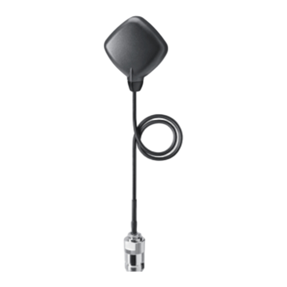
ANT1390-4ML
Antenna for global navigation satellite systems
RUGGEDCOM antenna for use in GPS, GLONASS and Galileo sys-
tems
Copyright © Siemens Canada Limited 2015
All rights reserved
The reproduction, transmission or use of this document or its con-
tents is not permitted without express written authority. Offenders
will be liable for damages. All rights, including rights created by
patent grant or registration of a utility model or design, are re-
served.
Disclaimer of Liability
We have checked the contents of this manual for agreement with
the hardware and software described. Since deviations cannot be
precluded entirely, we cannot guarantee full agreement. However,
the data in this manual are reviewed regularly and any necessary
corrections included in subsequent editions. Suggestions for im-
provement are welcome.
Technical data subject to change without prior notice.
Siemens Canada Limited
Industry Sector
300 Applewood Crescent
Concord, Ontario
Canada, L4K 5C7
Classification of safety-related notices
This manual contains notices which you should observe to ensure
your own personal safety, as well as to protect the product and
connected equipment. Notices relating to your personal safety are
highlighted by a warning triangle; notices relating to property dam-
age only do not have a warning triangle. Warnings in descending
order according to the degree of danger are shown as follows.
Danger
indicates that death or severe personal injury will result if
proper precautions are not taken.
Warning
indicates that death or severe personal injury can result if
proper precautions are not taken.
Caution
with a warning triangle indicates that minor personal injury
can result if proper precautions are not taken.
Caution
without a warning triangle indicates that damage to prop-
erty can result if proper precautions are not taken.
Notice
indicates that an undesirable result or status can occur if
the relevant notice is ignored.
A5E35553757A-AA
Release 01/2015
English
1
General safety notices
Warning
Devices installed outdoors must be within the area cov-
ered by a lightning protection system. Make sure that all
conducting systems entering from outdoors can be pro-
tected by a lightning protection potential equalization
system.
When implementing your lightning protection concept,
make sure you adhere to the VDE 0182 or IEC 62305
standard.
Warning
The device (and its components) may only be used for the
application described in the catalog or the operating in-
structions. It may only be combined with devices or com-
ponents of other manufacturers that have been approved
and released by Siemens.
Correct and safe operation of the device is guaranteed
only when it is transported, stored, set up, installed, used
and maintained according to the recommendations.
Qualified personnel
Only qualified personnel should be allowed to install and
work on this equipment. Qualified persons in the sense of the
safety-related notices in this manual are defined as persons
who are authorized to commission, to ground, and to tag cir-
cuits, equipment, and systems in accordance with estab-
lished safety practices and standards.
2
Components of the product
The following components are supplied with the
ANT1390-4ML:
•
1 ANT1390-4ML Antenna
•
Operating Instructions
Please check that the consignment you have received is
complete. If it is not complete or there are signs of external
damage, please contact your supplier or your local Siemens
office.
3
Installation
Select a mounting location at which the reception of the
antenna in the direction of the sky is not hindered.
Make sure that there are no metallic surfaces above the
antenna.
Magnetic
1. Take the antenna out of the protective sleeve.
2. Do not remove the protective foil to avoid damaging the
mounting surface.
3. Select a level, ferrous surface with a diameter of at least
11 cm.
4. Secure the antenna horizontally on the mounting sur-
face using the magnets, see dimension drawing
With screws
1. Take the antenna out of the protective sleeve.
2. Remove the protective foil.
3. Screw the antenna horizontally at the specified points
with M2.5 screws, see dimension drawing
.
.
Advertisement

Related Manuals for Siemens RUGGEDCOM ANT1390-4ML


Summary of Contents for Siemens RUGGEDCOM ANT1390-4ML
- Page 1 Please check that the consignment you have received is Technical data subject to change without prior notice. complete. If it is not complete or there are signs of external damage, please contact your supplier or your local Siemens office. Siemens Canada Limited...
- Page 2 Technical specifications Filter graph Frequency range 1575.42 MHz ± 10 MHz Antenna gain 3 dBic (at 90°) -2 dBic (at 20°) Polarization Circular, clockwise Connector N-Connect, female Cable RG-174 cable, 30 cm Type of antenna booster 2-stage, low-noise Boost 20 dB (at 3.3 VDC) Supply voltage 2.7 –...
Need help?
Do you have a question about the RUGGEDCOM ANT1390-4ML and is the answer not in the manual?
Questions and answers