
Related Manuals for Avtech DGM1104QS


Summary of Contents for Avtech DGM1104QS
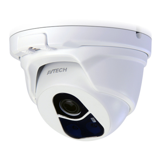
- Page 1 Dome IP CAMERA SERIES OPERATION GUIDE Please read instructions thoroughly before operation and retain it for future reference. dm_1304_qs_1104_qs_1304se_m1203_V1.2...
- Page 2 IMPORTANT SAFEGUARD All lead-free products offered by the company comply with the requirements of the European law on the Restriction of Hazardous Substances (RoHS) directive, which means our manufacture processes and products are strictly “lead-free” and without the hazardous substances cited in the directive. The crossed-out wheeled bin mark symbolizes that within the European Union the product must be collected separately at the product end-of-life.
- Page 3 MP EG4 Licensing THIS PRODUCT IS LICENSED UNDER THE MPEG4 VISUAL PATENT PORTFOLIO LICENSE FOR THE PERSONAL AND NON-COMMERCIAL USE OF A CONSUMER FOR (i) ENCODING VIDEO IN COMPLIANCE WITH THE MPEG4 VISUAL STANDARD (“MPEG-4 VIDEO”) AND/OR (ii) DECODING MPEG4 VIDEO THAT WAS ENCODED BY A CONSUMER ENGAGED IN A PERSONAL AND NON-COMMERCIAL ACTIVITY AND/OR WAS OBTAINED FROM A VIDEO PROVIDER LICENSED BY MPEG LA TO PROVIDE MPEG4 VIDEO.
-
Page 4: Table Of Contents
TABLE OF CONTENTS 1. OVERVIEW ............................1 1.1 Product Features ............................. 1 1.2 Package Content ............................. 1 1.3 Cable Overview ............................1 2. CAMERA ACCESS WITH INTERNET EXPLORER ................2 2.1 Camera Login ............................2 2.2 Control Panel Overview ........................... 2 2.3 Digital PTZ (DPTZ) Operations (For selected models only) .............. - Page 5 APPENDIX 3 POE CONNECTION ...................... 33 APPENDIX 4 API ID APPLICATION FOR SMS MESSAGING ............. 34 APPENDIX 5 Q&A ..........................36 APPENDIX 6 RECORDING TIME TABLE.................... 38 APPENDIX 7 PREREQUISITES FOR NETWORK SHARE ..............39 A7.1 Check PC IP Address.......................... 39 A7.2 Create "Administrator"...
-
Page 6: Overview
1. OVERVIEW 1.1 Product Features ONVIF standard supported to simplify system integration POE (Power-over-Ethernet) support to eliminate the use of power cables and reduce installation costs IR LEDs built-in for night surveillance DWDR to increase image recognizability in overexposure and dark areas. ... -
Page 7: Camera Access With Internet Explorer
2. CAMERA ACCESS WITH INTERNET EXPLORER This network camera can be accessed via Microsoft Internet Explorer and iOS / Android mobile devices with our self-developed program “EagleEyes” installed depending on different using situations. Before using the camera, make sure you have configured the network settings, and the network connection is fine. For network configurations, please refer to: “ADVANCED NETWORK SETUP”... - Page 8 Function Icon User Level Description Supervisor / Power User Switch to the live view page. Live / Normal User / Guest Enter the event record list for video playback. Supervisor / Power User Backup* For details, please refer to “2.4 Event Record Search & Playback (For selected models only)’...
-
Page 9: Digital Ptz (Dptz) Operations (For Selected Models Only)
2.3 Digital PTZ (DPTZ) Operations (For selected models only) This camera has PTZ capability, i.e. digital PTZ (hereafter called “DPTZ”), for wide area monitoring. Click “DPTZ” to show the DPTZ control panel. FUNCTION ICON DESCRIPTION When is selected, the moving control panel will be shown to move the picture after zoom-in is Moving panel performed. -
Page 10: Event Record Search & Playback (For Selected Models Only)
2.4 Event Record Search & Playback (For selected models only) Note: To save more recorded data, it’s recommended to use this camera with a compatible NVR. Click to jump to the next / previous time interval in an hour, for example, 11:00 ~ 12:00 or 14:00 Previous / Next Hour ~ 15:00, and start playing the earliest event video clip recorded during this whole hour. -
Page 11: Camera Configurations
3. CAMERA CONFIGURATIONS Users can further configure this network camera by accessing via Internet Explorer. 3.1 System configuration menu Click “Config.” to enter the configuration page. The functions are categorized into seven menus: Network, Camera, ONVIF, Trigger and General. For details about “Network”, please refer to “3.2 Network” at page 8. ... - Page 12 Main Menu Sub-Menu Reference 1. Enable / disable the motion / internal alarm detection. 2. Set the motion detection area. Trigger Trigger 3. Configure how the camera reacts for any event. Configure to receive active alarm notifications within 5 seconds after event occurrence on Push Video* mobile devices.
-
Page 13: Network
3.2 Network 3.2.1 Network You can set the network configuration of the network camera depending on your network type. For details, please refer to “Advanced Network Setup” from www.surveillance-download.com/user/dm1304.swf. Note: EaZy Networking & IPv6 are supported only for selected models to quickly connect the device to the internet. -
Page 14: Sntp
3.2.4 SNTP SNTP (Simple Network Time Protocol) is used to synchronize your camera time with the networked computer.. Function Description Once users choose the time zone, the network camera will adjust the local area time of the system automatically. NTP Server Simply use the default SNTP server (For example, tock.stdtime.gov.tw) or change to another server with which users are familiar. -
Page 15: Sms
3.2.7 SMS Note: Before using this function, you need to apply an account and get an API ID from the mobile messaging company, such as Clickatell and EVERY8D. For details, please refer to “APPENDIX 4 API ID APPLICATION FOR SMS MESSAGING” at page 34. Enter the detailed information needed for text messaging, and click “Save”... -
Page 16: Upnp / Bonjour
Function Description Filter Configuration Error Count Set the maximum count for login failure. When the maximum count is reached, the IP address trying to access the network camera will be locked. Error Lock Time Set the lock time in minutes when the maximum count of error login for an IP address is reached. Echo Request Select “Non-Block”... -
Page 17: Rtp
Port Mapping (Available only in UPnP) This function can eliminate the need to additionally access the router for port forwarding. For details, please refer to “Advanced Network Setup” from www.surveillance-download.com/user/dm1304.swf. Note: Before using this function, make sure your router supports UPnP, and this function is enabled. If not, please access your router additionally for port forwarding. -
Page 18: Snmp (For Selected Models Only)
3.2.11 SNMP (For selected models only) SNMP, Simple Network Management Protocol, is used to facilitate the exchange of management information between network-attached devices, and network administrators could use it to monitor those devices. The SNMP consists of three basic components: Network-management systems (NMSs) to monitor and control the managed devices. -
Page 19: Ieee 802.1X (For Selected Models Only)
3.2.12 IEEE 802.1X (For selected models only) The settings here enable the camera to access a network protected by 802.1X/EAPOL (Extensible Authentication Protocol Over LAN). Note: For authentication to work properly, it's important to synchronize the time in the camera with an NTP server. -
Page 20: Network Failure Detection
To use this function, make sure: A PC is installed in the same LAN environment as this camera, and you know the IP address of the PC. A PC account is created as “Administrator” with a user name and password. ... -
Page 21: Roi (For Selected Models Only)
3.3.3 ROI (For selected models only) ROI, Region of Interest, is used to reinforce the image quality of the selected area(s). Users could specify two areas in the camera view. 3.3.4 Color Adjust the color performance from Brightness, Contract, Saturation, and Hue. Click and drag the slider to preview the color change on the right side of this page and adjust the image color. -
Page 22: Advanced
3.3.6 Advanced Adjust the camera parameters if necessary. Note: The functions available depend on the model number used. Item Description Fixed Shutter* Shutter Speed is a function that can adjust the duration of the electronic shutter to produce optimum image quality. Select the shutter speed suitable for your environment. -
Page 23: Privacy Mask (For Selected Models Only)
Item Description Select ”ON” or ”Auto” to enable the defog function in poor weather conditions such as fog, smog or smoke. The captured Defog* image can be improved. Angle of view* This function is used to slightly calibrate the viewing angle when the focal length and focus adjustment is completed. Select “Down”... -
Page 24: Record (For Selected Models Only)
3.5 Record (For selected models only) 3.5.1 Record Enable or disable the record function. When “Enable” is set to “No”, the record function is disabled even if you enable it in other configuration pages. Select if the data should be overwritten when the memory storage is full. ... -
Page 25: Trigger
3.7 Trigger 3.7.1 Trigger You can configure how this camera reacts when there’s a PIR or motion event. Detect Item Description Motion Enable or disable motion detection. Motion detection is not supported when the stream format is Motion JPEG. When “Enable”... -
Page 26: Push Video (For Selected Models Only)
3.7.2 Push Video (For selected models only) “Push Video” is an active notification system integrated with smart phones. Users are able to receive alarm notifications within 5 seconds after event occurrence, check what happened with video playback, and take actions immediately. Note: For Push Video to work properly, make sure the record function is on in “Record”... -
Page 27: Snapshot
3.7.3 Snapshot Enable this function to schedule the camera to take snapshots periodically or at a specific time, and send the snapshots to E-Mail, FTP, and / or Network Share for backup. Note: Before using E-Mail, FTP and Network Share, make sure the related configurations are done in “Network”... -
Page 28: Time
3.8.2 Time Set daylight saving time and the current time, and click “Save” to confirm. Function Description Time Configuration Set the current date. Date Set the current time. Time Daylight Saving Time Configuration Specify whether to use daylight saving time (Enable / Disable). Daylight Saving Time If this function is enabled, set the time period (Start Time / End Time), and adjust the daylight saving time in hours (Adjust Time). -
Page 29: Online
3.8.4 Online You can check the current online user(s) with respective online information, and customize how many users can access your device at the same time. Note: The online users set in “Max Online User” cannot exceed the number this device supports. For details, please check the specifications of your device. -
Page 30: Google Maps
How to modify or delete an existing account Step1: Select the account you want to modify or delete. Step2: To modify the account, click “Edit” to change the settings, and click “Save”. To remove the account, click “Delete”. Note: It’s not allowed to remove an account when there’s only one account in the account list. 3.8.6 Google Maps This function is used to let you know where the network camera is. -
Page 31: Maintenance
3.8.7 Maintenance Firmware Upgrade This function is used when users need to upgrade the camera for function scalability. Note: Before using this function, make sure you have the correct upgrade files provided by your installer or distributor. Note: The event videos saved in the camera will be removed after firmware upgrade. Make sure you’ve copied important events to your PC before firmware upgrade. -
Page 32: Appendix 1 Product Specifications
APPENDIX 1 PRODUCT SPECIFICATIONS Model 1 Model 2 ▓ Network LAN Port LAN Speed 10/100 Based-T Ethernet DDNS, PPPoE, DHCP, NTP, SNTP, TCP/IP, ICMP, SMTP, FTP, HTTP, RTP, RTSP, RTCP,IPv4, Bonjour, UPnP, Supported Protocols DNS,UDP,IGMP, QoS, SNMP ONVIF Compatible YES (Profile S) Number of Online Users (1) Multiple user access levels with password Security... - Page 33 Model 3 Model 4 ▓ Network LAN Port LAN Speed 10/100 Based-T Ethernet DDNS, PPPoE, DHCP, NTP, SNTP, TCP/IP, ICMP, SMTP, FTP, HTTP, RTP, RTSP, RTCP,IPv4, Bonjour, UPnP, Supported Protocols DNS,UDP,IGMP, QoS, SNMP ONVIF Compatible YES (Profile S) Number of Online Users (1) Multiple user access levels with password Security (2) IP address filtering...
- Page 34 Model 5 ▓ Network LAN Port LAN Speed 10/100 Based-T Ethernet DDNS, PPPoE, DHCP, NTP, SNTP, TCP/IP, ICMP, SMTP, FTP, HTTP, RTP, RTSP, RTCP,IPv4, Bonjour, UPnP, Supported Protocols DNS,UDP,IGMP, QoS, SNMP ONVIF Compatible YES (Profile S) Number of Online Users (1) Multiple user access levels with password Security (2) IP address filtering...
- Page 35 Model 6 ▓ Network LAN Port LAN Speed 10/100 Based-T Ethernet DDNS, PPPoE, DHCP, NTP, SNTP, TCP/IP, ICMP, SMTP, FTP, HTTP, RTP, RTSP, RTCP,IPv4, Bonjour, UPnP, Supported Protocols DNS,UDP,IGMP, QoS, SNMP ONVIF Compatible YES (Profile S) Number of Online Users (1) Multiple user access levels with password Security (2) IP address filtering...
-
Page 36: Appendix 2 Bit Rate Table For Reference
APPENDIX 2 BIT RATE TABLE FOR REFERENCE The data below is for reference only. The bit rates listed here may vary depending on the resolution, image quality & frame rate you choose, the complexity of your monitoring area, and how often the moving objects show in your monitoring area. Testing Environment Place: Office Entrance ... - Page 37 Resolution Quality Frame Rate (Dynamic) kbps (Static) kbps SXGA Best 1/15 High Normal Basic Best High Normal Basic QVGA Best High Normal Basic...
-
Page 38: Appendix 3 Poe Connection
APPENDIX 3 POE CONNECTION This device supports PoE (Power-over-Ethernet), developed by the IEEE802.3af or IEEE802.3at task force, and power can be supplied over the same network (Ethernet) cable as the one used to connect to Internet. No power cable is needed. Below shows two examples of POE application for reference. When your router / hub supports POE connection ... -
Page 39: Appendix 4 Api Id Application For Sms Messaging
APPENDIX 4 API ID APPLICATION FOR SMS MESSAGING To allow the camera automatically sending a text message when an event happens, you need to apply an API ID from a mobile messaging company first, such as Clickatell or EVERY8D. Below shows an example of how to get an API ID from Clickatell. Note: The SMS messaging may not be totally free. - Page 40 Step4: In your account, find “Connection Status” and create a connection (API ID). Step5: Select “HTTP/S”. Give a meaning name for this connection, and click “Submit and Get API ID”. Step5: An API ID will be generated as follows. Note: Note down the API ID for SMS notification setting later.
-
Page 41: Appendix 5 Q&A
APPENDIX 5 Q&A I can connect to this camera in my house or office where it’s installed with wireless network. But when I leave my house or office, I can’t connect to it from my mobile phone (with 3G network), or other PC (connected to Internet). - Page 42 Step2: Click “Sign-in & Security.” Step3: Roll down to the bottom of the page and check the “Allow less secure apps.”...
-
Page 43: Appendix 6 Recording Time Table
APPENDIX 6 RECORDING TIME TABLE Below shows the estimated total recording time for each recording resolution. The recording time per resolution is the average value collected from the both alarm trigger conditions indicated in “Testing Environment”, and is for reference only. The time may vary depending on the resolution, image quality &... -
Page 44: Appendix 7 Prerequisites For Network Share
APPENDIX 7 PREREQUISITES FOR NETWORK SHARE “Push Video” is an active notification system, different from traditional FTP & Email notification methods. It’s more active and stable, but also easier to be affected by your network bandwidth. A7.1 Check PC IP Address Note: The instructions below are taking Windows 7 and 8 for an example. -
Page 45: A7.3 Share Folder
Step2: Set a user name, and choose “Administrator” for this account. Then, click “Create Account”. Step3: Set the password, and click “Create Account”. A7.3 Share Folder Note: The instructions below are taking Windows 7 and 8 for an example. Step1: Right-click the folder you want to use to save snapshots for “Network Share”, and choose “Properties”. Step2: In “Share Properties”, select the tab of “Sharing”, and choose “Share…”. - Page 46 Step3: Choose the account you want to share with, and click “Share” to save.
-
Page 47: Appendix 8 Enable Push Video
APPENDIX 8 ENABLE PUSH VIDEO A8.1 What’s Push Video “Push Video” is an active notification system, different from traditional FTP & Email notification methods. It’s more active and stable, but also easier to be affected by your network bandwidth. When “Push Video” is enabled and any alarm event occurs, you’ll be able to receive notifications on your iPhone / iPad / Android mobile device within 5 seconds. -
Page 48: A8.3.2 From Android Mobile Device
A8.3.2 From Android Mobile Device In the address book, switch “Guard” from “OFF” to “ON”. -
Page 49: Appendix 9 Eazy Networking
Note: This function is for selected models only. EaZy Networking is a free P2P cloud service to connect AVTECH devices to the Internet automatically by plug-and-play, enabling you to check the live view via your mobile device or laptop at anytime. - Page 50 Step3: Open Internet Explorer, and enter the IP address and port number you found to enter the login page. The format is: http://ipaddress:port. Enter the user name and password to login. The default user name and password are both ”admin”. Then, choose ”Config.”...
- Page 51 Step7: (Optional) If your camera has LED indicators, make sure both indicators are always on, and select “Yes” to continue. Step8: Enter or scan the MAC address. - Find the address sticker on the camera starting with “000E53”, and type it manually. Or, - Access the camera as shown in Step3 to scan the QR code.
-
Page 52: A9.1.2 Checking Remaining Data Allowance
A9.1.2 Checking Remaining Data Allowance Step1: Log into the cloud service. Step2: Select “Details” to go to account information, and select “Available Data Allowance”. A9.1.3 Sharing Cloud Device Access with Other Account(s) Note: One cloud device could be shared up to 30 cloud accounts, but the access to the device might be failed because it is still restricted to the maximum online user setup of the device. - Page 53 Step4: Check again the account with which you want to share your cloud device, and select “Next” to confirm and continue. Step5: Specify the access permission of the specified account, which account’s data allowance should be consumed after access successfully, and how long the account is allowed to stay after access successfully. Who should pay data allowance: ...
-
Page 54: A9.2 Via Internet Explorer On Pc / Laptop
A9.2 Via Internet Explorer on PC / Laptop Note: EaZy Networking setup via a web browser is only available on Internet Explorer. A9.2.1 Setup Step1: Find a laptop and connect it to the same router physically (with a RJ45 network cable) or wirelessly as the one to which the camera is connected. - Page 55 Step4: Open Internet Explorer on a PC / laptop, and enter https://ez.eagleeyes.tw. In the login page, register an account for “Cloud Service”. If you’ve got an account, please just log in. Note: You PC must be connected to Internet. Step4: Click + on the left pane, and you’ll be prompted to install plugins: EaZy Control and EaZy Wizard. Please follow the instructions to install these two plugins to ensure the service works properly.
- Page 56 Step7: When your device is found, you’ll be directed to the next page to change the device title if you want. Note: The device name changed here will be fixed and can’t be changed later. Click “Apply” to continue. You’ll be prompted to confirm if you want to remove the default user name and password.
-
Page 57: A9.2.2 Checking Remaining Data Allowance
A9.2.2 Checking Remaining Data Allowance Step1: Log into the cloud service. Step2: Select “Account Information” on the top right corner to go to account information, and select “Available Data Allowance”. A9.2.3 Sharing Cloud Device Access to Other Account(s) Note: One cloud device could be shared up to 30 cloud accounts, but the access to the device might be failed because it is still restricted to the maximum online user setup of the device. - Page 58 Step5: Specify the access permission of the specified account, which account’s data allowance should be consumed after access successfully, and how long the account is allowed to stay after access successfully. Who should pay data allowance: Who should pay The order to consume data allowance data allowance The free data allowance provided by the device ->...
-
Page 59: A9.3 Icons
The cloud icon will be grayed out if the EaZy server can’t be connected. You’ve shared the access right of the device with other cloud account via Buddy (AVTECH Cloud Service). Depending on the device color The icon will be grayed out if you disable the device share.
Need help?
Do you have a question about the DGM1104QS and is the answer not in the manual?
Questions and answers