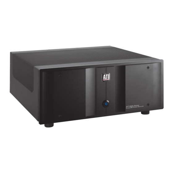
Summary of Contents for ATI Technologies AT1820 Series
- Page 1 AT1820 SERIES CLASS AB 2 TO 7-CHANNEL POWER AMPLIFIER OWNER’S GUIDE AT1820 Manual Rev-05/21...
-
Page 2: Safety Warning
PLEASE READ FIRST SAFETY INSTRUCTIONS Read all the safety and operating instructions before connec- tion or using the AT1820 amplifier. All warnings on the unit and in this operating manual should be adhered to. All operating and use instructions should be followed. CAUTION: To reduce the risk of electrical shock, do not remove the cover (or back). -
Page 3: Table Of Contents
Table of Contents SAFETY WARNING ......................... 1 SAFETY INSTRUCTIONS ....................... 1 Table of Contents ..........................2 AT1820 Identification Record ......................2 Introduction ............................3 Features and Testing..........................3 Unpacking ............................3 Placement ............................. 3 Rack Mounting ............................. 4 Owner’s Guide Conventions ........................ 4 Front Panel Layout .......................... -
Page 4: Introduction
The carton and packing materials used in ship- ping your new amplifier were specially designed to The AT1820 Series is comprised of six models; the last protect it from the shock and vibration of shipping. We digit in the model number is the number of channels in strongly suggest that you save the carton and packing the amplifier. -
Page 5: Owner's Guide Conventions
Owner’s Guide Conventions For clarity purposes, references to buttons and LED’s will be shown in bold capital letters. Front Panel Layout ATI LOGO. ILLUMINATED POWER SWITCH. When the amplifier is plugged in and idle, the ILLUMINATED POWER SWITCH is off. When the ILLUMINATED POWER SWITCH is depressed, the illumination of the switch be- comes constant and the amplifier begins the turn-on process. -
Page 6: Rear Panel Layout
Rear Panel Layout F. Circuit Breaker / Main Power Switch A. Balanced (XLR) Audio Inputs Use the BALANCED INPUT jacks to connect to the G. AC Inlet outputs of a preamplifier or other control device with Use the included power cord to connect your amplifier XLR outputs. -
Page 7: Connecting Your Amplifier
Correct polarity of connections are important to main- Connecting Your Amplifier tain proper speaker phasing. When speaker phasing is When making connections between any source compo- correct, all speakers move in and out at the same time, nents and the amplifier, or when making connections to preserving the imaging of the program material. -
Page 8: Power Control Connections
may vary from this configuration. To assure proper phase and the main power switch / circuit breaker is in the on connections, and optimal performance, consult the identifi- position, the amplifier is in the standby mode and cation plate on your speaker terminals, or the speaker’s draws less than 1 watt from the wall outlet. -
Page 9: Ac Line Connector And Power Cord
ATI Service Information To determine if a cable TV connection is responsible The AT1820 series does not contain any user servicea- for the hum, first turn all components off. Disconnect ble parts inside. If you suspect a problem that may re-... - Page 10 WARNING: If you suspect that the grounding system in your home’s electrical wiring is causing the hum problem, it is important that you do not make any changes to the wiring yourself. Only a licensed electri- cian should make any changes to household wiring, and they must be made in full compliance with all local building, safety and electrical codes.
-
Page 11: Appendix A - Troubleshooting Guide
Appendix A - Troubleshooting Guide Your ATI amplifier is designed for trouble free operation. If you follow the instructions in this manual you should enjoy many years of high quality listening enjoyment. However, as with any sophisticated electronic device, there may be oc- casional problems upon initial installation, or during the life of the unit. -
Page 12: Appendix C - Specifications
Appendix C - Specifications (Specifications subject to change without notice) One Single-ended (RCA) jack per channel & One Balanced (XLR) jack per channel Analog Audio Inputs Slide Switch to choose jack Input Impedance 28 kΩ Nominal 1.6 Volts for rated power Input Sensitivity Into 8 ohms 28dB... -
Page 13: Appendix D - Power Requirements & Consumption
Appendix D - Power Requirements & Consumption 117V AC or 230V; 50/60 Hz Power Requirements Factory Configured Power Consumption Less than 1W at Standby; 1800W maximum AT1822 AT1823 AT1824 AT1825 AT1826 AT1827 Standby <1 Watts Idle 110W 150W 7.65A 11.2A 17.5A 11.4A @ Rated Power (8Ω) -
Page 14: Warranty Information
90-Day Limited Warranty Transferability Terms and Conditions The above warranties are transferable to subsequent owners as (7-Year Optional Extended Warranty) long as all of the conditions are met under the Optional Extend- ed Warranty Program. The warranty is not transferable if the This ATI product is warranted against defects in materials and unit was originally purchased from an unauthorized seller.


Need help?
Do you have a question about the AT1820 Series and is the answer not in the manual?
Questions and answers