Subscribe to Our Youtube Channel
Summary of Contents for ATI Technologies AT4000
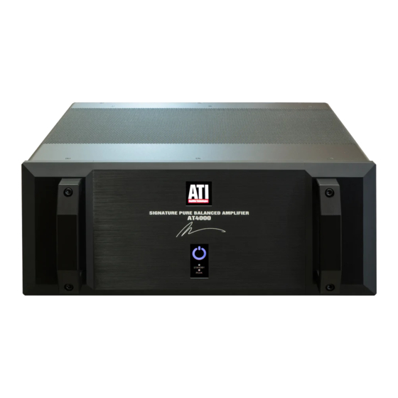
- Page 1 AT4000 SIGNATURE SERIES PURE BALANCED™ 2 TO 7-CHANNEL POWER AMPLIFIER OWNER’S GUIDE...
-
Page 2: Please Read First
Please Read First Safety Instructions WARNING: TO REDUCE THE RISK OF FIRE OR ELECTRIC SHOCK, DO NOT EXPOSE THIS UNIT TO RAIN OR MOISTURE. Read all the safety and operating instructions before connecting or using this unit. CAUTION: To reduce the risk of electrical shock, do not remove the cover (or back). -
Page 3: Handles And Rack Mounting
The handles on the AT4000 Series may be removed by using an In order to receive the maximum performance from your Allen wrench. Carefully remove the four socket-head cap screws... -
Page 4: Connecting Your Amplifier
Getting to Know the Rear Panel A. Balanced XLR Audio Inputs F. Remote Trigger Input Use the BALANCED INPUT jacks to connect to the outputs Use the REMOTE TRIGGER jack to connect to a compatible of a preamplifier or other control device with XLR outputs. preamplifier, source device, or other product with a 3.3-24 VDC output. -
Page 5: Input Connections
Correct polarity connections are important to maintain proper Input Connections speaker phasing. When speaker phasing is correct, all speakers move in and out at the same time, preserving the imaging of the Connecting the amplifier to your source equipment is sim- program material. - Page 6 AT-4002 AT-4003 AT-4004 Page 6...
- Page 7 AT-4005 AT-4006 AT-4007 Page 7...
-
Page 8: Amplifier Operation
The amplifier will automatically go into a standby mode in a few The power cord for your AT4000 series amplifiers may be moments. plugged in to a single 15 Amp circuit (120VAC) OR 8 Amp Peak Indicator Light (230VAC). -
Page 9: Main Circuit Breaker
Main Circuit Breaker Your amplifier is supplied with a heavy-duty magnetic cir- The AT4000 series amplifiers do not contain any user serviceable cuit breaker/power switch. If power to your amplifier is parts. If you suspect a problem that may require service assis- interrupted, inspect the circuit breaker on the rear of the tance, please contact us at support@ati-amp.com or by telephone... -
Page 10: A Few Words About Hum And Noise
A Few Words About Hum and Noise The ultimate solution to this type of problem is to re-wire your Audible hum, or a discernible low frequency noise, is one house with an isolated, star type grounding configuration. We of the most common problems in audio/video systems. This recognize, however, that this may be impractical and expensive. -
Page 11: Power Amplifier Specifications
Power Amplifier Specifications Series AT4000 2 to 7 Number of Channels 250 Watts EIA 1kHz Output Power at 8 Ohms* EIA 1kHz Output Power at 4 Ohms* 375 Watts 200 Watts 300 Watts 1.95 Volts Input Sensitivity for Full Rated Power... - Page 12 90-Day Limited Warranty Transferability Terms and Conditions The above warranties are transferable to subsequent owners as long as all of the conditions are met under the Optional Extend- (7-Year Optional Extended Warranty) ed Warranty Program. The warranty is not transferable if the unit was originally purchased from an unauthorized seller.


Need help?
Do you have a question about the AT4000 and is the answer not in the manual?
Questions and answers