Table of Contents
Advertisement
Quick Links
Advertisement
Table of Contents

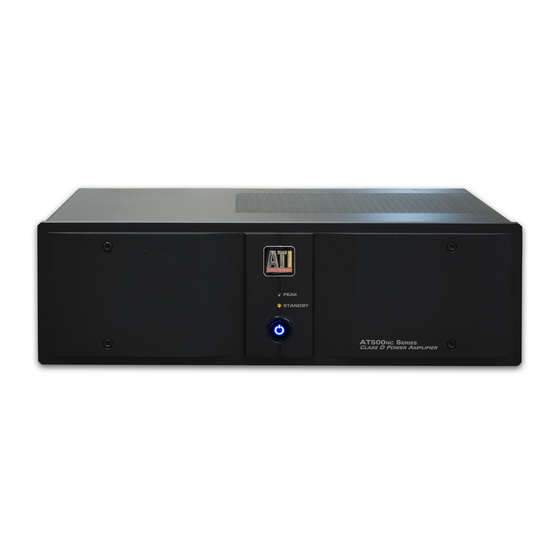
Summary of Contents for ATI Technologies AT500NC Series
- Page 1 AT500 SERIES CLASS D 2 TO 8-CHANNEL POWER AMPLIFIER OWNER’S GUIDE...
-
Page 2: Safety Warning
PLEASE READ FIRST SAFETY INSTRUCTIONS Read all the safety and operating instructions before connec- CAUTION tion or using the AT500 amplifier. RISK OF ELECTRIC SHOCK All warnings on the unit and in this operating manual should DO NOT OPEN be adhered to. All operating and use instructions should be followed. -
Page 3: Table Of Contents
Table of Contents SAFETY WARNING ......................... 1 SAFETY INSTRUCTIONS ....................... 1 Table of Contents ..........................2 AT500 Identification Record ......................2 Introduction ............................3 Features and Testing..........................3 Unpacking ............................3 Placement ............................. 3 Handles and Rack Mounting ........................ 4 Owner’s Guide Conventions ........................ -
Page 4: At500 Nc
AT500 Series Power Amplifiers requirements. This procedure includes the following: All assembled circuit boards are given a thorough Congratulations! Thank you for purchasing an ATI visual inspection and are then performance tested. AT500 Power Amplifier, one of the most advanced audio components available. -
Page 5: Handles And Rack Mounting
To order, call your dealer or ATI and order SKU # / Handles and Rack Mounting Model “NC RMK”. You will need to specify which model and color of AT500 you own so we can pro- The AT500 Series amplifiers can be rack mounted vide you with the correct length of rack ear and the cor- into a standard 19-inch rack with the addition of rack rect color of handle and hardware. -
Page 6: Rear Panel Layout
Rear Panel Layout E. Ground Terminal A. Balanced (XLR) Audio Inputs Use to connect to other chassis where necessary. Use the BALANCED INPUT jacks to connect to the outputs of a preamplifier or other control device with F. Fuse XLR outputs. Replace only with the correct type and rating. -
Page 7: Connecting Your Amplifier
cable. Wire with a gauge of 16 may be used for short Connecting Your Amplifier runs of less than twenty feet. We do not recommend When making connections between any source compo- that you use any wires with an AWG equivalent of 18 nents and the amplifier, or when making connections to or higher due to the power loss and degradation in per- any speaker, be certain that both the input devices and... -
Page 8: Power Control Connections
will insure that the maximum surface area of the plug is adapter to the trigger-input jack on the back panel of in contact with the jack. Be certain to observe proper the amplifier. The amplifier will now turn on and off polarity. -
Page 9: Automatic On
process is complete, the front panel switch will illumi- Care and Maintenance nate fully, the STANDBY LED will turn off and the Cleaning amplifier will enter playback mode. To turn the unit off, press the Power button again. The power switch When the unit becomes dirty, wipe it with a clean, soft, indicator light will dimly illuminate and pulse slowly. - Page 10 Suggestion #2: Turn off all components in your system, and then dis- connect the input cables at the amplifier. Turn the am- plifier back on, and see if the hum is still present. If the hum disappears, the fault may be in the input cables used.
-
Page 11: Appendix A - Troubleshooting Guide
Appendix A - Troubleshooting Guide Your ATI amplifier is designed for trouble free operation. If you follow the instructions in this manual you should enjoy many years of high quality listening enjoyment. However, as with any sophisticated electronic device, there may be oc- casional problems upon initial installation, or during the life of the unit. -
Page 12: Appendix C - Specifications
Appendix C - Specifications (Specifications subject to change without notice) One Single-ended (RCA) jack per channel & One Balanced (XLR) jack per channel Analog Audio Inputs Toggle Switch to choose jack Input Impedance 20 kΩ Balanced for each phase AT52Xnc - 1.5V input for 200W RMS AT54Xnc - 2.35V RMS input for 500W Input Sensitivity 8 ohms... -
Page 13: Appendix D - Power Requirements & Consumption
Appendix D - Power Requirements & Consumption 117V AC (90V-132V) or 230V (200V-260V); 50/60 Hz Power Requirements Amplifier automatically selects proper voltage range Less than 1W at Standby; 1800W maximum Power Consumption AT522 AT523 AT524 AT525 AT526 <1 Watts Standby Idle Sleep 5.7A... -
Page 14: Warranty Information
90-Day Limited Warranty Transferability Terms and Conditions The above warranties are transferable to subsequent owners as (7-Year Optional Extended Warranty) long as all of the conditions are met under the Optional Extend- ed Warranty Program. The warranty is not transferable if the This ATI product is warranted against defects in materials and unit was originally purchased from an unauthorized seller.


Need help?
Do you have a question about the AT500NC Series and is the answer not in the manual?
Questions and answers