Table of Contents
Advertisement
Quick Links
MiniLine-2
G
D
ENERAL
ESCRIPTION
A compact size, light weight, simple mounting onto the
DIN-rail and the utilization of only quality components
are what makes the MiniLine power supplies so easy to
use and install within seconds.
A rugged electrical and mechanical design as well as a
high immunity against electrical disturbances on the
mains provides reliable output power. This offers
superior protection for equipment which is connected
to the public mains network or is exposed to a critical
industrial environment.
The MiniLine series offers output voltages from 5 to
56Vdc and a power rating from 15W to 120W.
The supplementary MiniLine decoupling diode module
MLY10.241 allows building of redundant systems or to
protect against back-feeding voltages.
O
N
RDER
UMBERS
Power Supply
ML60.121
Accessory
MLY10.241
ZM3.WALL
Nov. 2015 / Rev. 1.4 DS--ML60.121-EN
All parameters are specified at 12V, 4.5A, 230Vac 50Hz input, 25°C ambient and after a 5 minutes run-in time unless otherwise noted.
12-15V Standard unit
Redundancy Module
Wall mount bracket
www.pulspower.com Phone +49 89 9278 0
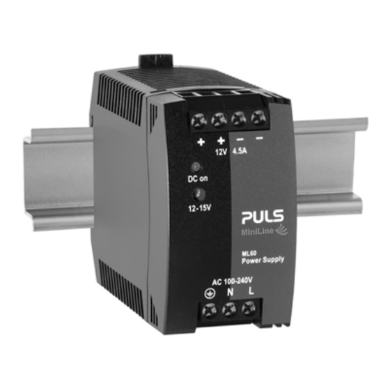
12V, 4.5A, S
P
S
OWER
UPPLY
100-240V Wide Range Input
NEC Class 2 Compliant
Adjustable Output Voltage
Efficiency up to 87.2%
Low No-load Losses and Excellent Partial-load Efficiency
Compact Design, Width only 45mm
Full Power between -10°C and +60°C
Large International Approval Package
3 Year Warranty
S
-
D
HORT
FORM
Output voltage
DC 12V
Adjustment range
12 - 15V
Output current
4.5A at 12V
3.6A at 15V
Output power
54W
Output ripple
< 50mVpp
Input voltage
AC 100-240V
Mains frequency
50-60Hz
AC Input current
0.91 / 0.54A
Power factor
0.58 / 0.5
AC Inrush current
typ. 16 / 32A
DC Input
88-375Vdc
Efficiency
85.3 / 87.2%
Losses
9.3 / 7.9W
Temperature range -10°C to +70°C
Derating
1.4W/°C
Hold-up time
typ. 25 / 113ms
Dimensions
45x75x91mm
Weight
250g / 0.55lb
M
ARKINGS
Ind. Cont. Eq. UL 508
Class I Div 2
Germany
ML60.121
P
I
INGLE
HASE
NPUT
ATA
20Hz to 20MHz
-15% / +10%
AC 100V mains
requires derating
±6%
at 120 / 230Vac
at 120 / 230Vac
peak value at 120
/ 230Vac 40°C
and cold start
below 130Vdc
derating required
at 120 / 230Vac
at 120 / 230Vac
operational
+60 to +70°C
at 120 / 230Vac
WxHxD
UL 60950-1
Marine
NEC
Class 2
EMC, LVD
1/23
Advertisement
Table of Contents

Related Manuals for Puls MiniLine-2 ML6040FE-R52


Summary of Contents for Puls MiniLine-2 ML6040FE-R52
- Page 1 ML60.121 12V, 4.5A, S MiniLine-2 INGLE HASE NPUT OWER UPPLY 100-240V Wide Range Input NEC Class 2 Compliant Adjustable Output Voltage Efficiency up to 87.2% Low No-load Losses and Excellent Partial-load Efficiency Compact Design, Width only 45mm Full Power between -10°C and +60°C Large International Approval Package 3 Year Warranty ENERAL...
-
Page 2: Table Of Contents
The information presented in this document is believed to be accurate and reliable and may change without notice. The housing is patent by PULS (US patent No US D442,923S). No part of this document may be reproduced or utilized in any form without permission in writing from the publisher. -
Page 3: Intended Use
ML60.121 12V, 4.5A, S MiniLine-2 INGLE HASE NPUT 1. I NTENDED This device is designed for installation in an enclosure and is intended for the general use such as in industrial control, office, communication, and instrumentation equipment. Do not use this power supply in equipment, where malfunction may cause severe personal injury or threaten human life. -
Page 4: Ac-Input
ML60.121 12V, 4.5A, S MiniLine-2 INGLE HASE NPUT 3. AC-I NPUT AC input nom. AC 100-240V -15% / +10%, TN/TT/IT-mains AC input range 85-264Vac continuous operation, see Fig. 3-3 for de-rating requirements for AC 100V mains. 264–300Vac < 0.5s Allowed voltage L or N to earth max. -
Page 5: Input Inrush Current
ML60.121 12V, 4.5A, S MiniLine-2 INGLE HASE NPUT Fig. 3-5 De-rating requirements for low input voltages Allowable Output Power Input Voltage 85Vac 90Vac 108Vac 4. I NPUT NRUSH URRENT A NTC limits the input inrush current after turn-on of the input voltage. The inrush current is input voltage and ambient temperature dependent. -
Page 6: Output
ML60.121 12V, 4.5A, S MiniLine-2 INGLE HASE NPUT 5. O UTPUT Output voltage nom. Adjustment range min. 12-15V guaranteed max. 16.2V *) at clockwise end position of potentiometer Factory setting 12.0V ±0.2%, at full load, cold unit Line regulation max. 10mV 85-264Vac Load regulation... -
Page 7: Hold-Up Time
The power supply can also be supplied from a DC source. Use a battery or similar DC source. For other sources contact PULS. Connect the + pole to L and the – pole to N. Connect the PE terminal to an earth wire or to the machine ground. -
Page 8: Efficiency And Power Losses
ML60.121 12V, 4.5A, S MiniLine-2 INGLE HASE NPUT 8. E FFICIENCY AND OWER OSSES AC 100V AC 120V AC 230V Efficiency typ. 83.5% 85.3% 87.2% at 12V, 4.5A (full load) Power losses typ. 0.45W 0.5W 0.85W at 0A typ. 4.2W 3.9W 4.2W at 12V, 2.25A (half load) -
Page 9: Functional Diagram
ML60.121 12V, 4.5A, S MiniLine-2 INGLE HASE NPUT 9. F UNCTIONAL IAGRAM Fig. 9-1 Functional diagram Input Rectifier Input Fuse & Output Power & Filter Converter Input Filter Inrush Limiter Output Output Over- Voltage Voltage Protection Regulator 10. F RONT IDE AND LEMENTS Fig. -
Page 10: Terminals And Wiring
ML60.121 12V, 4.5A, S MiniLine-2 INGLE HASE NPUT 11. T ERMINALS AND IRING All terminals are easy to access when mounted on the panel. Input and output terminals are separated from each other (input below, output above) to help in error-free wiring. Input Output screw terminals... -
Page 11: 13. Emc
Criterion A 70% of 200Vac 140Vac, 500ms Criterion A Voltage interruptions EN 61000-4-11 0Vac, 5000ms Criterion C Input voltage swells PULS internal standard 300Vac, 500ms Criterion A Powerful transients VDE 0160 over entire load range 750V, 1.3ms Criterion A Criterions: Power supply shows normal operation behavior within the defined limits. -
Page 12: Environment
ML60.121 12V, 4.5A, S MiniLine-2 INGLE HASE NPUT 14. E NVIRONMENT Operational temperature -10°C to +70°C (14°F to 158°F) reduce output power according Fig. 14-1 Storage temperature -40°C to +85°C (-40°F to 185°F) for storage and transportation Output de-rating 1.4W/°C 60-70°C (140°F to 158°F) Humidity 5 to 95% r.H. -
Page 13: Protection Features
PELV IEC/EN 60204-1, EN 50178, IEC 62103, IEC 60364-4-41 Class of protection PE (Protective Earth) connection required II (with restrictions) for use without PE connection contact PULS Isolation resistance > 5MOhm Input to output, 500Vdc Touch current (leakage current) typ. 0.13mA / 0.29mA 100Vac, 50Hz, TN-,TT-mains / IT-mains typ. -
Page 14: Dielectric Strength
ML60.121 12V, 4.5A, S MiniLine-2 INGLE HASE NPUT 17. D IELECTRIC TRENGTH The output voltage is floating and has no ohmic connection to the ground. Type and factory tests are conducted by the manufacturer. Field tests may be conducted in the field using the appropriate test equipment which applies the voltage with a slow ramp (2s up and 2s down). -
Page 15: Approvals
ML60.121 12V, 4.5A, S MiniLine-2 INGLE HASE NPUT 18. A PPROVALS EC Declaration of The CE mark indicates conformance with the Conformity - EMC directive and the - Low-voltage directive (LVD). See Declaration of Conformity (DoC) for further information. IEC 60950-1 CB Scheme, Edition Information Technology Equipment... -
Page 16: Physical Dimensions And Weight
ML60.121 12V, 4.5A, S MiniLine-2 INGLE HASE NPUT 20. P HYSICAL IMENSIONS AND EIGHT Weight 250g / 0.55lb DIN-Rail Use 35mm DIN-rails according to EN 60715 or EN 50022 with a height of 7.5 or 15mm. The DIN-rail height must be added to the unit depth (91mm) to calculate the total required installation depth. -
Page 17: Accessory
ML60.121 12V, 4.5A, S MiniLine-2 INGLE HASE NPUT 21. A CCESSORY 21.1. ZM3.WALL – W OUNT RACKET DIN-Rail bracket for wall or panel mount: The picture of the power supply is for representation only Hole diameter: 4.2mm 21.2. MLY10.241 - R EDUNDANCY ODULE The MLY10.241 is a dual redundancy module, which has two diodes with a common cathode included. -
Page 18: Application Notes
ML60.121 12V, 4.5A, S MiniLine-2 INGLE HASE NPUT 22. A PPLICATION OTES 22.1. P URRENT APABILITY Solenoids, contactors and pneumatic modules often have a steady state coil and a pick-up coil. The inrush current demand of the pick-up coil is several times higher than the steady-state current and usually exceeds the nominal output current. -
Page 19: Charging Of Batteries
ML60.121 12V, 4.5A, S MiniLine-2 INGLE HASE NPUT 22.3. C HARGING OF ATTERIES The power supply can be used to charge 12V lead-acid or maintenance free batteries. Instructions for charging batteries (float charging): Ensure that the ambient temperature of the power supply is below 45°C Set output voltage (measured at no load and at the battery end of the cable) very precisely to the end-of-charge voltage. -
Page 20: Parallel Use For Redundancy
ML60.121 12V, 4.5A, S MiniLine-2 INGLE HASE NPUT 22.6. P ARALLEL SE FOR EDUNDANCY Voltage Power supplies can be paralleled for redundancy to gain higher system Monitor availability. Redundant systems require a certain amount of extra power to support the load in case one power supply unit fails. The simplest way is Output IN 1 IN 2... -
Page 21: Series Operation
From a safety standpoint, the unit is internally designed according to the requirements for Protection Class 1 and 2. Please contact PULS if you do not plan to use the PE terminal. A different marking of the front foil is then required. -
Page 22: Use In A Tightly Sealed Enclosure
ML60.121 12V, 4.5A, S MiniLine-2 INGLE HASE NPUT 22.12. U SE IN A IGHTLY EALED NCLOSURE When the power supply is installed in a tightly sealed enclosure, the temperature inside the enclosure will be higher than outside. In such situations, the inside temperature defines the ambient temperature for the power supply. The following measurement results can be used as a reference to estimate the temperature rise inside the enclosure. -
Page 23: Mounting Orientations
ML60.121 12V, 4.5A, S MiniLine-2 INGLE HASE NPUT 22.13. M OUNTING RIENTATIONS Mounting orientations other than input terminals on the bottom and output on the top require a reduction in continuous output power or a limitation in the maximum allowed ambient temperature. The amount of reduction influences the lifetime expectancy of the power supply.
Need help?
Do you have a question about the MiniLine-2 ML6040FE-R52 and is the answer not in the manual?
Questions and answers