Table of Contents
Advertisement
Quick Links
Instructions/Parts
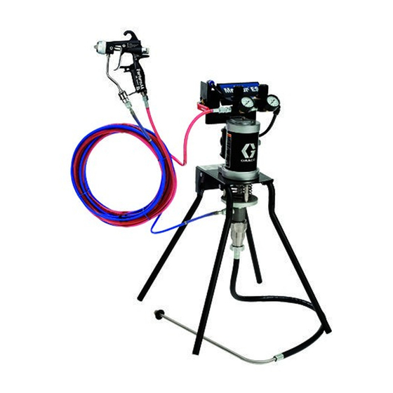
Merkur
Spray Packages
For low-volume fine finish spray applications. For professional use only.
Important Safety Instructions
Read all warnings and instructions in this
manual. Save these instructions.
15:1 Spray Packages
30:1 Spray Packages
100 psi (0.7 MPa, 7.0 bar) Maximum Air Inlet Pressure
See page 3 for model information, including maximum fluid
working pressure.
®
ES
ti15589a
3A0732P
EN
ti15590a
II 2 G Ex h T5 Gb X
Advertisement
Table of Contents

Subscribe to Our Youtube Channel
Related Manuals for Graco Merkur ES 24W285


Summary of Contents for Graco Merkur ES 24W285
- Page 1 Instructions/Parts ® Merkur Spray Packages 3A0732P For low-volume fine finish spray applications. For professional use only. Important Safety Instructions Read all warnings and instructions in this manual. Save these instructions. 15:1 Spray Packages 30:1 Spray Packages 100 psi (0.7 MPa, 7.0 bar) Maximum Air Inlet Pressure See page 3 for model information, including maximum fluid working pressure.
-
Page 2: Table Of Contents
Air Line Accessories ..... . 7 Graco Information ......44 Wall Mount Packages . -
Page 3: Models
Models Models Maximum Fluid Working Pressure Package Series Ratio psi (MPa, bar) Package Type Mounting Material 24F150 15:1 1500 (10.3, 103) Air-assisted G15 Carbide Wall Plated Steel 24F151 15:1 1500 (10.3, 103) Air-assisted G15 Carbide Stand Plated Steel 24F152 30:1 3000 (20.7, 207) Air-assisted Wall... -
Page 4: Warnings
Warnings Warnings The following warnings are for the setup, use, grounding, maintenance, and repair of this equipment. The exclama- tion point symbol alerts you to a general warning and the hazard symbols refer to procedure-specific risks. When these symbols appear in the body of this manual, refer back to these Warnings. Product-specific hazard symbols and warnings not covered in this section may appear throughout the body of this manual where applicable. - Page 5 Warnings WARNING WARNING WARNING WARNING EQUIPMENT MISUSE HAZARD Misuse can cause death or serious injury. • Do not operate the unit when fatigued or under the influence of drugs or alcohol. • Do not exceed the maximum working pressure or temperature rating of the lowest rated system component.
- Page 6 Warnings 3A0732P...
-
Page 7: Installation
Installation Installation Prepare the Operator • The spray gun (H) dispenses the fluid. The gun houses the spray tip (not shown), which is available in a wide range of sizes for different spray patterns All persons who operate the equipment must be trained and rates of flow. -
Page 8: Wall Mount Packages
Installation Wall Mount Packages 2. Air and fluid hoses: Static electricity may build up when fluids flow through pumps, hoses, and spray- ers. At least one hose must be electrically conduc- 1. Be sure the wall can support the weight of the tive, with a maximum of 500 ft. -
Page 9: Setup
Installation Setup 1. See F . 2. Attach one end of fluid hose (K) to pump 4. Attach remaining end of the air hose to air inlet at outlet (or optional inline fluid filter outlet). base of gun (H). 2. Attach other end of fluid hose to gun fluid inlet at 5. -
Page 10: Operation
Operation Operation Pressure Relief Procedure Trigger Lock Trapped air can cause the pump to cycle unexpect- edly, which could result in serious injury from skin See F . 3. Always engage gun trigger lock when you injection, splashing or moving parts. stop spraying to prevent gun from being triggered acci- dentally by hand or if dropped or bumped. -
Page 11: Install The Spray Tip
Operation 2. See F . 2. Close gun air regulator (E) and pump air Adjust the Atomization regulator (F) by turning knobs counterclockwise reducing pressure to zero. Close bleed-type air valve (D). 3. Connect air line to bleed type air valve. NOTE: Use this procedure with airless and air-assisted 4. -
Page 12: Adjust The Spray Pattern
Operation Adjust the Spray Pattern 3. See F . 4. For narrower pattern, turn pattern adjustment valve knob (AA) counterclockwise (out). If pattern is still not narrow enough, increase air pressure to gun slightly or use different size tip. NOTE: Use this procedure with air-assisted spray guns only. -
Page 13: Maintenance
Maintenance Maintenance Tighten Threaded Connections Flush at the lowest pressure possible. Flush with a fluid that is compatible with the fluid you are pumping and with the wetted parts in your system. Check with your Before each use, check all hoses for wear or damage. fluid manufacturer or supplier for recommended flushing Replace as necessary. -
Page 14: Troubleshooting
Fluid dried on the displacement rod (119). Clean; keep the packing nut wet-cup filled with Graco throat seal liquid (TSL). Pump operates but does not prime. Held open or worn ball check valves or pis- Clear valve; replace packings. See page ton packings. -
Page 15: Repair
• Always use Genuine Graco Parts and Accessories, available from your Graco distributor. If you supply 1. Stop the pump. your own accessories, be sure they are adequately sized and pressure rated for your system. -
Page 16: Disassemble The Pump
Repair Disassemble the Pump 3. Install the male gland (114‡) in the cylinder (105). Install the throat packings in the following order with the lips facing down: blue UHMWPE (106‡), leather NOTE: Pump Repair Kits are available. See page 31 to (113‡), UHMWPE, leather, UHMWPE. - Page 17 Repair 2. Tighten the jam nut (13). Torque to 65-75 ft-lb 4. Push the retaining spring (19) into place to cover the (88-102 N•m). pin. 3. Align the hole in the displacement rod with the hole 5. Fill throat packing nut wet-cup with TSL to prevent in the air motor rod.
-
Page 18: Repair Air Valve
Repair Repair Air Valve 311 312 Replace Complete Air Valve 305 1. Stop the pump. Follow Pressure Relief Procedure, page 10. 2. Disconnect the air line to the motor. 3. See F . 14 on page 23. Remove four screws (211). 309†... - Page 19 Repair 310 †306 307 304 303 311 312 305 †308 302 †309 †308 307 †306 ti16213a 310 Apply lubricant. . 9. Air Valve Assembly 3A0732P...
-
Page 20: Replace Pilot Valves
Repair Reassemble the Air Valve 7. Install the spring (311). Lubricate and install the air valve cup (312), see F . 11. Align the small 1. See F . 9. Lubricate detent cam (304) and install round magnet with the air inlet. into housing. -
Page 21: Disconnect The Air Motor
Repair Disconnect the Air Motor 1. Stop the pump. 2. Flush the pump, if possible (see page 13). Follow Pressure Relief Procedure, page 10. 3. Disconnect the air hose, fluid hose, and suction hose. 4. See F . 12. Push the safety spring (9) down and hold to access the coupling pin (18). -
Page 22: Repair Air Motor
Repair Repair Air Motor Reassemble the Air Motor NOTE: For easier reassembly, start with the top cover (210) turned over on the workbench and assemble the air motor upside-down. NOTE: Complete Air Motor Replacement Kits are avail- able. Order 24G693 (2.5 in. motor) or 24G694 (3.5 in. 1. - Page 23 Repair Apply lubricant. 204* *230 208* 202* *202 *217 *207 209*† 208* *207 TI16130a . 14. Air Motor Assembly 3A0732P...
- Page 24 Repair 5. Lubricate and install the o-ring (202*) on the bottom 10. Install the tie bolts (212) hand tight. cover (201). 11. Install two gaskets (208*) on the manifold (220). 6. Carefully push the threaded end of the rod (218) up Install the manifold (220).
-
Page 25: Parts
Parts Parts Package Parts NOTE: For hose and gun, see page 29. Part of air motor (7) Detail of Stand Kit (2) 1 (Ref) TI16438a TI16129a 3A0732P... - Page 26 Parts Package Parts 15:1 Ratio Pumps Package Ref. No. Description 24F150 24F151 24W281 24F158 24F159 24W283 24X311 BRACKET, wall 24H102 24H102 24H102 24H102 24H102 24H102 24H102 KIT, stand; includes items 3, 4, 5, 6, and 24F164 24F164 24F164 24F164 43 below, and 418 on page 36 PLUG 108175 108175...
- Page 27 Parts Package Parts 30:1 Ratio Pumps Package Ref. No. Description 24F152 24F153 24W287 24F154 24F155 24F156 24F157 24W285 BRACKET, wall 24H102 24H102 24H102 24H102 24H102 24H102 24H102 24H102 KIT, stand; includes items 3, 4, 5, 6, and 24F164 24F164 24F164 24F164 24F164 43 below, and 418 on page 36 PLUG...
- Page 28 Parts 3A0732P...
-
Page 29: Hose And Gun
Parts Hose and Gun Air-Assisted Packages Airless Packages TI16231a TI16230a Package 24F150 24F152 24F156 24F158 24F151 24F153 24F154 24F157 24F159 Ref. No. Description 24W281 24W287 24F155 24W285 24W283 24X311* HOSE, air, gun 241811 241811 241811 241811 GUN, air-assisted, G15; see 3A0149 24C853 24C853 GUN, air-assisted, G40;... -
Page 30: Displacement Pump Parts
Parts Displacement Pump Parts Part No. 24G701, Plated Steel Part No. 24G702, Stainless Steel ‡102 ‡104 ‡112 15, see page 26 ‡106 113‡ ‡114 107‡ 109 116‡ 117 111‡ ‡121 ‡126 125‡ ‡122 ‡123 ‡120 ti32016a 3A0732P... - Page 31 Parts Displacement Pump Parts Part No. 24G701, Plated Steel Part No. 24G702, Stainless Steel Ref. Description 24G701 24G702 102‡ BUTTON, plug NUT, packing; plated steel 193047 NUT, packing; sst 24H161 104‡ O-RING; buna-N; 1.262 in. (32.05 mm) OD CYLINDER, pump 17D481 24G706 106‡...
-
Page 32: Air Motor Parts
Parts Air Motor Parts Part No. 24G693, 2.5 in. (63.5 mm) Part No. 24G694, 3.5 in. (88.9 mm), shown 204* *230 208* 202* *202 *217 *207 209*† 208* *207 TI16130a 3A0732P... - Page 33 Parts Air Motor Parts Part No. 24G693, 2.5 in. (63.5 mm) Part No. 24G694, 3.5 in. (88.9 mm), shown Ref. Description 24G693 24G694 KIT, cover, bottom; includes 202 (qty 1), 24G695 24G696 203, 207, 213 (qty 1), and 217 202* O-RING, cover Not sold separately.
-
Page 34: Air Valve Parts
Parts Air Valve Parts 310 †306 307 304 303 311 312 305 †308 302 †309 †308 307 †306 ti16213a 310 3A0732P... - Page 35 Parts Air Valve Parts Complete Air Valve Replacement Kit 24A351 To replace the complete air valve, order Air Valve Replacement Kit 24A351. The kit includes items 301-312 below, and items 209 and 211 on page 33. Air Valve Repair Kits Air valve parts are not sold individually.
-
Page 36: Air Control Parts
Parts Air Control Parts Part No. 24H162, Air-Assisted, Wall Mount Part No. 24H163, Air-Assisted, Stand Mount Part of 402 TI16132a Connect tubing (406) between these two fittings. Used on stand mount units only. Part No. 24H164, Airless, Wall Mount Part No. 24H165, Airless, Stand Mount Connect tubing (406) between these two fittings. - Page 37 Parts Air Control Parts Part No. 24H162, Air-Assisted, Wall Mount Part No. 24H163, Air-Assisted, Stand Mount Part No. 24H164, Airless, Wall Mount Part No. 24H165, Airless, Stand Mount Ref. Description 24H162 24H163 24H164 24H165 Qty BRACKET, handle 24H105 24H105 24H105 24H105 REGULATOR, air 15T499 15T499 REGULATOR, air...
-
Page 38: Kits And Accessories
Kits and Accessories Kits and Accessories Kit Description Part No. Airless to Air-Assisted Conversion Kit 24F161 Inline Fluid Filter, stainless steel 24F271 Inline Fluid Filter, aluminum 24F272 24F148 Standard Suction Hose, 5 gal. (19 l), 3/8 in. (10 mm) OD 24F149 Suction Hose, 5 gal. -
Page 39: Package Dimensions
Package Dimensions Package Dimensions A, inch B, inch Package (mm) (mm) inch (mm) inch (mm) 20.2 (513) Wall Mount 29.0 (737) 17.4 (442) 18.4 (467) Stand Mount 29.0 (737) 17.4 (442) 26.5 (673) Stand Mount with Hopper Front View Top View ti16288a ti16287a Package Weights... -
Page 40: Wall Bracket Mounting Hole Diagram
Wall Bracket Mounting Hole Diagram Wall Bracket Mounting Hole Diagram 2 x 0.35 in. (9 mm) 2 x 0.281 (9/32) in. (7 mm). For wall mount only. 4.40 in. (112 mm) 2.69 in. (68 mm) 2 x 0.62 in. (16 mm) 2 x 0.48 in. -
Page 41: Technical Data
Technical Data Technical Data Maximum fluid working pressure 15:1 Pumps......1500 psi (10.3 MPa, 103 bar) 30:1 Pumps. -
Page 42: Performance Charts
Performance Charts Performance Charts 15:1 Ratio Pumps A = 100 psi (0.7 MPa, 7 bar) B = 70 psi (0.5 MPa, 5 bar) C = 40 psi (0.3 MPa, 3 bar) = fluid flow = air flow Cycles per Minute 1400 10.5 (10, 100) -
Page 43: 30:1 Ratio Pumps
Performance Charts 30:1 Ratio Pumps A = 100 psi (0.7 MPa, 7 bar) B = 70 psi (0.5 MPa, 5 bar) C = 40 psi (0.3 MPa, 3 bar) = fluid flow = air flow Cycles per Minute 3000 18.0 (21, 210) (0.5) 2500... -
Page 44: Graco Standard Warranty
With the exception of any special, extended, or limited warranty published by Graco, Graco will, for a period of twelve months from the date of sale, repair or replace any part of the equipment determined by Graco to be defective.
Need help?
Do you have a question about the Merkur ES 24W285 and is the answer not in the manual?
Questions and answers