Graco EM 390 Instructions And Parts List
Portable/electric airless paint sprayer 2500 psi (172 bar) maximum working pressure
Hide thumbs
Also See for EM 390:
- Instructions for use manual (28 pages) ,
- Instructions-parts list manual (29 pages)
Table of Contents
Advertisement
INSTRUCTIONS-PARTS LIST
EM 390
PORTABLE/ELECTRIC
AIRLESS PAINT SPRAYER
2500 psi (172 bar) MAXIMUM WORKING PRESSURE
U.S. Patent No. 4,323,741
Upright Carts
Model 231–001, Series B
Basic sprayer, without hose or gun
Model 231–390
Complete sprayer with hose, "Flex" gun,
Reverse–A–Clean IV DripLess Tip Guard,
and 517 size SwitchTip , and is CSA listed
Model 231–018
Same as Model 231–390 except has "Contractor" gun
Lo–Boy Carts
Model 220–726, Series C
Basic sprayer, without hose or gun
Model 231–051
Complete sprayer with hose, "Flex" gun,
Reverse–A–Clean IV DripLess Tip Guard,
and 517 size SwitchTip , and is CSA listed
See Table Of Contents on page 36.
NOTE: This is an example of the DANGER label on your sprayer.
This label is available in other languages, free of charge.
See page 33 to order.
Spray painting, flushing or cleaning equipment with flammable liq-
uids in confined areas can result in fire or explosion.
Use outdoors or in extremely well ventilated areas. Ground equip-
ment, hoses, containers and objects being sprayed.
Avoid all ignition sources such as static electricity from plastic drop
cloths, open flames such as pilot lights, hot objects such as ciga-
rettes, arcs from connecting or disconnecting power cords or turn-
ing light switches on and off.
Failure to follow this warning can result in death or serious injury.
READ AND UNDERSTAND ALL LABELS AND INSTRUCTION MANUALS BEFORE USE
This manual contains IMPORTANT
WARNINGS and INFORMATION
READ AND RETAIN FOR REFERENCE
FIRE AND
EXPLOSION HAZARD
Liquids can be injected into the body by high pressure airless spray
or leaks – especially hose leaks.
Keep body clear of the nozzle. Never stop leaks with any part of the
body. Drain all pressure before removing parts.Avoid accidental trig-
gering of gun by always setting safety latch when not spraying.
Never spray without a tip guard.
In
case
of
accidental
skin
"Surgical Treatment".
Failure to follow this warning can result in amputation or serious
injury.
307–724
Rev H
Supersedes Rev F
(and Rev G – not published)
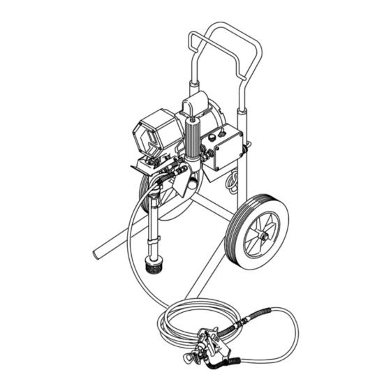
Model 231–390 shown
0663
SKIN INJECTION
HAZARD
injection,
seek
immediate
Advertisement
Table of Contents

Subscribe to Our Youtube Channel
Related Manuals for Graco EM 390


Summary of Contents for Graco EM 390
- Page 1 This manual contains IMPORTANT WARNINGS and INFORMATION READ AND RETAIN FOR REFERENCE EM 390 PORTABLE/ELECTRIC AIRLESS PAINT SPRAYER 2500 psi (172 bar) MAXIMUM WORKING PRESSURE U.S. Patent No. 4,323,741 Upright Carts Model 231–001, Series B Basic sprayer, without hose or gun Model 231–390...
-
Page 2: Pressure Relief Procedure
HIGH PRESSURE SPRAY CAN CAUSE SERIOUS INJURY. FOR PROFESSIONAL USE ONLY. OBSERVE ALL WARNINGS. Read and understand all instruction manuals before operating the equipment. FLUID INJECTION HAZARD General Safety This equipment generates very high fluid pressure. Spray from the gun, leaks or ruptured components can inject fluid through your skin and into your body, and cause extremely serious bodily injury, including the need for amputation. - Page 3 MOVING PARTS HAZARD Moving parts can pinch or amputate your fingers or other body parts. KEEP CLEAR of moving parts when starting or operating the sprayer. Follow the Pressure Relief Procedure on page 2 before checking or servicing any part of the sprayer, to prevent it from starting accidentally.
- Page 4 La pulvérisation à haute pression peut causer de blessures très graves. Réservé exclusivement à l’usage professionnel. Observer toutes les consignes de sécurité. Bien lire et bien comprendre tous les manuels d’instructions avant d’utiliser le matériel. RISQUES D’INJECTION Consignes générales de sécurité Cet appareil produit un fluide à...
- Page 5 RISQUES EN CAS DE MAUVAISE UTILISATION DU MATERIAL Consignes générales de sécurité Toute utilisation anormale de l’appareil du pulvérisation ou des accessoires comme, par exemple, la mise sous une pression excessive, les modifications de pièces, l’utilisation de produits chimiques et de matières incompatibles et l’utilisation de pièces usées ou abîmées peut causer des dégâts à...
- Page 6 EL ROCIADO A ALTA PRESION PUEDE CAUSAR GRAVES LESIONES. SOLO PARA USO PROFESIONAL. RESPECTE LOS AVISOS DE ADVERTENCIA. Lea y entienda todo el manual de instrucciones antes de manejar el equipo. PELIGRO DE INYECCION DE FLUIDO Seguridad general Este equipo general un fluido a una presión muy alta. El rociado de la pistola, los escapes de fluido o roturas de los componentes pueden inyectar fluido en la piel y el cuerpo y causar lesiones ex- tremadamente graves, incluyendo a veces la necesidad de am-...
- Page 7 PELIGRO POR MAL USO DEL EQUIPO Seguridad general Cualquier mal uso del equipo pulverizador o los accesorios, tal como sobre presurización, modificación de piezas, uso de mate- riales y productos químicos incompatibles, o utilización de pie- zas dañadas o desgastadas, puede hacen que se rompan y causen la inyección de fluido u otras lesiones corporales graves, incendio, explosión o daños a la propiedad.
- Page 8 WARNING If you are supplying your own hoses and spray gun, be sure the hoses are electrically conductive, that the gun has a tip guard, and that each part is rated for at least 2500 psi (172 bar) Maximum Working Pressure . This is to reduce the risk of se- rious bodily injury caused by static sparking, fluid injection or over-pressurization and rupture of the hose or gun.
- Page 9 FLUID FILTER DO NOT INSTALL A SHUT OFF DEVICE HERE PACKING NUT/WETCUP Keep 1/3 full with TSL MAIN FLUID HOSE (minimum 50 ft./15.2 m) Fig 9–1 Pressure Relief Procedure To reduce the risk of serious bodily injury, including in- jection; splashing in the eyes or on the skin; injury from moving parts or electric shock, always follow this pro- cedure whenever you shut off the sprayer, when checking or servicing any part of the spray system,...
- Page 10 1. Prime the sprayer with paint. a. Close the pressure drain valve. See Fig 10–2. b. Don’t install the spray tip yet! c. Put the suction tube into the paint container. You can hang the pail on the pail hanger. See Fig 10–2.
- Page 11 SPOTTY PATTERN – INCREASE PRESSURE Fig 11–1 ROTATE HANDLE 180 AND TRIGGER GUN TO REMOVE CLOG RETAINING NUT TIP GUARD SHOWN IN POSITION FOR A VERTICAL SPRAY PATTERN Fig 11–2 3. Adjust the spray pattern. a. Increase the pressure setting just until spray from the gun is completely atomized.
-
Page 12: Shutdown And Care
1. Check the packing nut/wetcup daily. First relieve the pressure; see page 9. Be sure the wetcup is 1/3 full of TSL at all times to help prevent fluid buildup on the piston rod and premature wear of packings. The packing nut should be tight enough to stop leakage, but no tighter. - Page 13 NOTE: The Pressure Relief Procedure Warning is on page 16. CAUTION NEVER leave water or water–base paint in the sprayer if there is the slightest change it could freeze. Flush out the water or water–base paint with mineral spirits. If water freezes in the pressure con- trol tube, it prevents the sprayer from being started, and causes serious damage to the pressure control.
-
Page 14: How To Flush
1. Relieve pressure. See page 16. 2. Remove the filter bowl and screen; see instruction manual 307–273, supplied. Clean the screen sepa- rately and install the bowl (only) to flush it. See Fig 14–1. 3. Close the pressure drain valve. 4. -
Page 15: Application Methods
Always hold the gun perpendicular to the work surface and at an even 12 to 14 in. (300 to 356 mm) from the sur- face you are spraying. See Fig 15–1. Begin moving the gun in a horizontal direction at a steady rate. -
Page 16: Troubleshooting Guide
Pressure Relief Procedure To reduce the risk of serious bodily injury, including fluid injection, splashing in the eyes or on the skin, or injury from moving parts, always follow this procedure when you shut off the sprayer, when checking, adjusting or cleaning the system, and when changing spray tips. - Page 17 PROBLEM CAUSE Electric motor labors when start- Motor capacitor has failed ing, and trips building circuit breaker or fuse Circuit board has failed Paint leaks into wet–cup Throat packings are worn or damaged Excessive surging from spray gun Spray tip or fluid filter is plugged Spray tip too big or worn Paint too viscous Wrong type hose...
-
Page 18: Displacement Pump
WARNING To reduce the risk of serious bodily injury, follow the Pressure Relief Procedure Warning on page 16 before checking or repairing any part of the spray system. Unplug the sprayer! Removing the Pump. See Fig 18–1. 1. Flush the sprayer. Relieve pressure. 2. - Page 19 *212 *209 LEATHER Lips must face down *211 *213 *208 LEATHER Lips must face up *220 *219 *204 Fig 19–1 Reassembly Procedure 1. Stack these parts one at a time onto the piston valve (224): backup washer (219*), U–cup seal (205*) lips down , and female gland (220*), alternate the polyeth- ylene and leather v–packings (217*, 208*) lips up, and then the male gland (213*).
- Page 20 REPLACING THE CONNECTING ROD and BEARING WARNING To reduce the risk of serious bodily injury, including fluid injection or splashing in the eyes or on the skin, or injury from moving parts, always follow the Pressure Relief Procedure Warning on page 16 before checking, adjusting, cleaning or shutting off the sprayer.
- Page 21 REPLACING THE DRIVE ASSEMBLY WARNING To reduce the risk of serious bodily injury, including fluid injection or splashing in the eyes or on the skin, or injury from moving parts, always follow the Pressure Relief Procedure Warning on page 16 before checking, adjusting, cleaning or shutting off the sprayer.
- Page 22 REPLACING THE ELECTRIC MOTOR & CAPACITOR WARNING To reduce the risk of serious bodily injury, including fluid injection or splashing in the eyes or on the skin, or injury from moving parts, always follow the Pressure Relief Procedure Warning on page 16 before checking, adjusting, cleaning or shutting off the sprayer.
- Page 23 REPLACING THE PRESSURE CONTROL & CIRCUIT BOARD WARNING To reduce the risk of serious bodily injury, including fluid injection or splashing in the eyes or on the skin, or injury from moving parts, always follow the Pressure Relief Procedure Warning on page 16 before checking, adjusting, cleaning or shutting off the sprayer.
-
Page 24: Pressure Control Adjustment
PRESSURE CONTROL ADJUSTMENT USE EXTREME CAUTION WHEN PERFORMING THIS ADJUSTMENT PROCEDURE to reduce the risk of a fluid injection injury or other serious bodily injury, which can result from component rupture, electric shock, fire, explosion or moving parts. This procedure sets the sprayer to 2500 psi (172 bar) MAXIMUM WORKING PRESSURE. - Page 25 PRESSURE CONTROL ADJUSTMENT NOTE: See Fig 25–1 for the following procedure. 4. Open the needle valve slightly. Turn the pressure con- trol knob (A) to the minimum setting. 5. Plug in the sprayer and turn the switch ON. Increase the pressure setting just enough to start the sprayer. Prime the hose, being sure to eliminate all air from the system.
- Page 26 PARTS DRAWING & LIST – PRESSURE CONTROL Part No. 215–860 Ref No. 50 Pressure Control Assembly Includes replaceable items 301 to 316, as listed below LABEL LABEL Ref 40 Ref 25 Part No. Description 100–035 SCREW, mach, pan hd, 8–32 x 5/16” 162–453* NIPPLE, 1/4 npsm x 1/4 npt 102–932 CONNECTOR, conduit, 90...
- Page 27 DISPLACEMENT PUMP PARTS DRAWING & LIST Model 218–215, Series C Carbon Steel Displacement Pump Includes items 201 to 224 NOTE: See the repair instructions for important torque values and procedures *212 *208 *209 218* *211 No. Part No. Description 201 180–656 PLUG 203 105–444* BALL,...
- Page 28 PARTS LIST – SPRAYER WITH UPRIGHT CART Model 231–001, Series B, Basic Sprayer Includes items 1 to 125 as listed below Part No. Description 065–099 CONDUIT, electrical 100–188 NUT, hex, 5/16–18 100–214 LOCKWASHER, spring, 3/8” 100–057 CAPSCREW, hex hd, 5/16–18 x 3/4”...
- Page 29 PARTS DRAWING – SPRAYER WITH UPRIGHT CART Model 231–001, Series B Basic Sprayer with Upright Cart DANGER LABEL, FRENCH SEE DETAIL BELOW 119a DETAIL A Ref 125 ID LABEL DANGER LABEL, ENGLISH Ref 1 WARNING LABEL Ref 7 Ref 52 Ref 52 0662...
- Page 30 PARTS LIST – SPRAYER WITH LO-BOY CART Model 220–726, Series C, Basic Sprayer Includes items 1 to 127 as listed below Part No. Description 065–099 CONDUIT, electrical 100–188 NUT, hex, 5/16–18 100–214 LOCKWASHER, spring, 3/8” 100–057 CAPSCREW, hex hd, 5/16–18 x 3/4” 156–823 UNION, 1/4 npt(m) x 1/4 npt(f) swivel...
- Page 31 PARTS DRAWING – SPRAYER WITH LO-BOY CART Model 220–726, Series C Basic Sprayer with Lo-Boy Cart 0661 DANGER LABEL, FRENCH SEE DETAIL BELOW DETAIL A Ref 125 ID LABEL DANGER LABEL ENGLISH 123c 123b 123a Ref 7 LABEL Ref 52...
- Page 32 PARTS DRAWING & LIST – COMPLETE SPRAYERS Model 231–390 Complete Upright Sprayer with Flex Gun Includes items 200 to 202, and 204 Model 231–018 Complete Upright Sprayer with Contractor Gun Includes items 201, 202, 204 and 205 Model 231–051 Complete Lo–Boy Sprayer with Flex Gun Includes items 200 to 203 PARTS DRAWING &...
- Page 33 ACCESSORIES DANGER LABELS The English language DANGER label shown on page 1 and the same label in French is on your spray- er. If you have painters who do not read English or French, order one of the following labels to apply to your sprayer.
-
Page 34: Technical Data
Maximum Working Pressure Motor ............Power Requirements Extension Cord Requirements Maximum Delivery... - Page 35 NOTES...
- Page 36 Warnings English ........French .
- Page 37 Width ..1/4 npsm(m) Weight carbon steel grounded, UHMWPE, leather EM390 0663 Upright LoBoy ..41 in. (1041 mm) 20 in (508 mm) ..
- Page 38 3Z7–724 Rev C Supplement to instruction manual 307–724. EM 390 Airless Paint Sprayer WARNING INJECTION HAZARD This form is only a quick reference to the features and frequently ordered parts of INSTRUCTIONS this sprayer. To reduce the risk of seri-...
Need help?
Do you have a question about the EM 390 and is the answer not in the manual?
Questions and answers