Table of Contents

Related Manuals for Federal Signal Corporation SELECTFONE SF-1245X-024


Summary of Contents for Federal Signal Corporation SELECTFONE SF-1245X-024
- Page 1 ® MODEL SELECTFONE INSTRUCTION SHEET FOR FEDERAL SELECTFONE Address all communications and shipments to: FEDERAL SIGNAL CORPORATION Electrical Products Division Service Department 2645 Federal Signal Drive University Park, IL 60466-3195...
-
Page 3: Specifications
® INSTRUCTION SHEET FOR FEDERAL SELECTFONE INTERCOM/PAGING SYSTEM SAFETY NOTICES WARNING Failure to follow all safety precautions and instructions may result in property damage, serious injury, or death to you or others. SAFETY MESSAGE TO INSTALLERS, USERS, AND MAINTENANCE PERSONNEL I. -
Page 4: Installation
Speaker Amplifier Output 12 Watts into 8 or 16 ohm load Voltage Gain 31dB adjustable Frequency Response 250-12000 Hz Distortion Less than 2% THD at 12 Watt, 1000Hz Input Impedance 50k ohm Output Impedance 8 ohm or 16 ohm Controls Speaker Volume Adjustable Handset Microphone... - Page 5 • All effective paging speakers produce loud sounds which may cause, in certain situations, permanent hearing loss. You should take appropriate precautions such as wearing hearing protection. • After installation, ensure that all set screws are properly tightened. • After installation, test the intercom to ensure that it is operating properly. •...
- Page 6 5. Place the rear of the housing against the mounting surface. Using the four mounting holes located in each corner of the enclosure as a template, scribe mounting hole locations on the mounting surface. CAUTION To avoid damage when drilling, ensure that both sides of the mounting surface are clear of any parts or wires.
- Page 7 handset handle, an “off hook” indicator LED, a page receive speaker with volume control, and 10 ft cable with 25-pin D-subminiature connector. To install the desktop unit follow the steps de- scribed below: 1. Install the remote subset enclosure within 10 ft of the desktop handset unit as described in Section A and make electrical connections as described in the Section E.
- Page 8 All SelectFone system stations are connected in parallel. 24VDC stations draw 1.5Amp. Max. current when page amplifier is driven by sine wave signal producing 12 watts in to an 8-ohm speaker. When planning 24VDC SelectFone system layout, careful consideration should be given to the power cable losses due to the voltage drop caused by cable resistance.
- Page 9 2. To make party line 1 connection, connect GREEN conductor of incoming and outgoing cable’s 18 AWG twisted pair GREEN ,WHITE/ GREEN to L1 and WHITE/GREEN conductor to L2 terminal at location identified as PARTY 1 be- tween terminal blocks L1 and L2. 3.
-
Page 10: Adjustments And Operation
CAUTION To avoid damage when drilling, ensure that both sides of the mounting surface are clear of any parts or wires. Drill the holes only through the desired surface. 3. The line balance assembly is supplied without conduit or cable entry holes. Drill or punch the necessary conduit or cable openings in the enclosure before mount- ing it to the surface. - Page 11 Pull out template for use during installation.
- Page 14 Pull out template for use during installation.
-
Page 15: Maintenance
the AC power circuit conductors running in parallel with the communication circuit conductors. At times this voltage can read 50 volts or more. This voltage is of no consequence because the page and channel lines are balanced twisted pair audio circuits. In an SelectFone system, the audio voltage across page line conductors or across any channel line conductors (L1 and L2) is of the order of 0.5 to 0.75 volts peak when someone is speaking into the handset microphone. -
Page 16: Service Parts
Representative or by calling the factory. At this time a brief explanation of the service requested, or the nature of the malfunction, should be provided. Address all communications and shipments to: FEDERAL SIGNAL CORPORATION Electrical Products Division Service Department 2645 Federal Signal Drive University Park, IL 60466-3195 VIII. - Page 17 SELECTFONE ENCLOSURE WITH COVER REMOVED (FIG. 1) 1/2 A SLO-BLO A.C. PAGE L1 PARTY1 L2 8.68" L1 PARTY2 L2 L1 PARTY3 L2 L1 PARTY4 L2 L1 PARTY5 L2 IN OUT ISO HANDSET SPKR MUTE PREAMP 5.00" 290A4034-01 A. Motherboard B. Power Supply Module C.
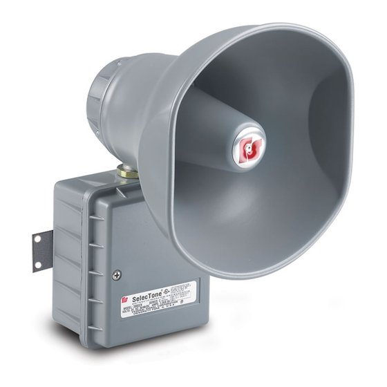
- Page 18 SELECTFONE INDOOR/OUTDOOR STATION MODEL SF-1245X & SF-1241X (FIG. 2) 14.6" ± .2" 6.5" ± .2 1.8" 12.6" ± .2" 10.00" 14.94" 290A4034-02 A. Enclosure Mounting Holes -12-...
- Page 19 PANEL CUT-OUT TEMPLATE FOR SF-1015P & SF-1011P (FIG. 3) 3.25" 0.25" 5.50" 0.25" 290A4034-03 A. Mounting Holes B. Cut-Out -13-...
- Page 20 -14-...
- Page 21 -15-...
- Page 22 -16-...
- Page 23 -17-...
- Page 24 LINE BALANCE ASSEMBLY MODEL SF-1000LB (FIG. 6) 290A4034-08 A. Mounting Holes B. Page Line Balance Adjustment 2561603B REV. B Printed 9/04 Printed in U.S.A.
Need help?
Do you have a question about the SELECTFONE SF-1245X-024 and is the answer not in the manual?
Questions and answers