
Related Manuals for GORMAN-RUPP PUMPS ULTRA V V4C60SC-B Series


Summary of Contents for GORMAN-RUPP PUMPS ULTRA V V4C60SC-B Series
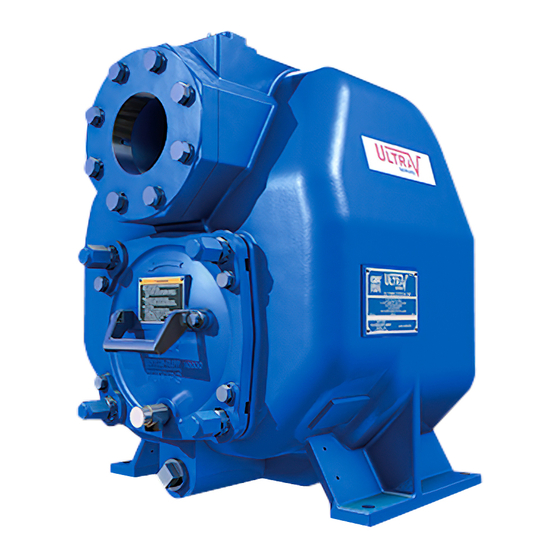
- Page 1 OM‐07337‐01 April 17, 2020 INSTALLATION, OPERATION, AND MAINTENANCE MANUAL WITH PARTS LIST ULTRA V SERIES PUMP MODEL V4C60SC‐B INCLUDING: /WW GORMAN‐RUPP PUMPS www.grpumps.com 2020 Gorman‐Rupp Pumps Printed in U.S.A.
- Page 2 Register your new Gorman‐Rupp pump online at www.grpumps.com Valid serial number and e‐mail address required. RECORD YOUR PUMP MODEL AND SERIAL NUMBER Please record your pump model and serial number in the spaces provided below. Your Gorman‐Rupp distributor needs this information when you require parts or service. Pump Model: Serial Number:...
-
Page 3: Table Of Contents
TABLE OF CONTENTS INTRODUCTION ..........PAGE I - 1 SAFETY - SECTION A . - Page 4 TABLE OF CONTENTS (continued) TROUBLESHOOTING - SECTION D ......PAGE D - 1 PREVENTIVE MAINTENANCE .
-
Page 5: Introduction
ULTRA V SERIES OM-07337 INTRODUCTION Thank You for purchasing a Gorman‐Rupp pump. HAZARD AND INSTRUCTION Read this manual carefully to learn how to safely DEFINITIONS install and operate your pump. Failure to do so could result in personal injury or damage to the The following are used to alert maintenance per... -
Page 6: Safety - Section A
ULTRA V SERIES OM-07337 SAFETY ‐ SECTION A This information applies to Ultra V Se the positive battery cable before per ries engine driven pumps. Refer to the forming any maintenance. Failure to do manual accompanying the engine be so may result in serious personal injury. fore attempting to begin operation. - Page 7 OM-07337 ULTRA V SERIES Do not operate an internal combustion After the unit has been installed, make engine in an explosive atmosphere. certain that the pump and all piping or When operating internal combustion hose connections are tight, properly engines in an enclosed area, make cer supported and secure before operation.
-
Page 8: Installation - Section B
ULTRA V SERIES OM-07337 INSTALLATION - SECTION B Review all SAFETY information in Section A. Check that the pump shaft rotates counter clockwise when facing the impeller. Since pump installations are seldom identical, this section offers only general recommendations and practices required to inspect, position, and ar... -
Page 9: Mounting
OM-07337 ULTRA V SERIES ing piping couplings in suction lines is not recom are not observed. Make certain that mended. hoists, chains, slings or cables are in good working condition and of suffi cient capacity and that they are posi Line Configuration tioned so that loads will be balanced Keep suction and discharge lines as straight as... -
Page 10: Strainers
ULTRA V SERIES OM-07337 stalled with the flat part of the reducers uppermost sump at a distance equal to 1 1/2 times the diame to avoid creating air pockets. Valves are not nor ter of the suction line. mally used in suction lines, but if a valve is used, install it with the stem horizontal to avoid air pock... -
Page 11: Discharge Lines
OM-07337 ULTRA V SERIES Figure 1. Recommended Minimum Suction Line Submergence vs. Velocity DISCHARGE LINES With high discharge heads, it is recommended that a throttling valve and a system check valve be in stalled in the discharge line to protect the pump from excessive shock pressure and reverse rota... -
Page 12: Automatic Air Release Valve
ULTRA V SERIES OM-07337 In low discharge head applications (less than 30 feet or 9 meters), it is recommended that the by pass line be run back to the wet well, and located 6 inches below the water level or cut‐off point of the If a manual shut‐off valve is installed in low level pump. -
Page 13: Air Release Valve Installation
OM-07337 ULTRA V SERIES Air Release Valve Installation tween the pump discharge port and the inlet side of the discharge check valve (see Figure 2). The inlet opening in the Air Release Valve is equipped with The Automatic Air Release Valve must be inde pendently mounted in a horizontal position be... -
Page 14: Coupled Drives
ULTRA V SERIES OM-07337 When mounted at the Gorman‐Rupp factory, driver and pump are aligned before shipment. Misalign ment will occur in transit and handling. Pumps must be checked and realigned before operation. Before checking alignment, tighten the foundation bolts. The pump casing feet and/or pedestal feet, and the driver mounting bolts should also be tightly secured. -
Page 15: Drive Belt Tensioning
OM-07337 ULTRA V SERIES Tighten the belts in accordance with the belt manu DRIVE BELT TENSIONING facturer's instructions. If the belts are too loose, they will slip; if the belts are too tight, there will be General Rules of Tensioning excessive power loss and possible bearing failure. -
Page 16: Operation - Section C
OM-07337 ULTRA V SERIES OPERATION - SECTION C Review all SAFETY information in Section A. Add liquid to the pump casing when: 1. The pump is being put into service for the Follow the instructions on all tags, labels and de first time. -
Page 17: Operation
OM-07337 ULTRA V SERIES If rotation is incorrect on a three‐phase motor, have pump components will deteriorate, and a qualified electrician interchange any two of the the liquid could come to a boil, build three phase wires to change direction. If rotation is pressure, and cause the pump casing to incorrect on a single‐phase motor, consult the liter... -
Page 18: Strainer Check
OM-07337 ULTRA V SERIES heated pump cautiously. It is recommended that This pump is equipped with an inspection cover to the pressure relief valve assembly be replaced at provide easy access to the interior of the pump for each overhaul, or any time the pump casing over removal of debris and to check the im... -
Page 19: Cold Weather Preservation
OM-07337 ULTRA V SERIES closed discharge throttling valve for BEARING TEMPERATURE CHECK long periods of time. If operated against a closed discharge throttling valve, Bearings normally run at higher than ambient tem pump components will deteriorate, and peratures because of heat generated by friction. the liquid could come to a boil, build Temperatures up to 160_F (71_C) are considered normal for bearings, and they can operate safely to... - Page 20 ULTRA V SERIES OM-07337 TROUBLESHOOTING - SECTION D Review all SAFETY information in Section A. Before attempting to open or service the pump: 1. Familiarize yourself with this manual. 2. Lock out or disconnect the power source to ensure that the pump will remain inoperative.
- Page 21 OM-07337 ULTRA V SERIES TROUBLE POSSIBLE CAUSE PROBABLE REMEDY PUMP STOPS OR Strainer clogged. Check strainer and clean if neces FAILS TO DELIVER sary. RATED FLOW OR PRESSURE Suction intake not submerged at Check installation and correct sub proper level or sump too small. mergence as needed.
- Page 22 ULTRA V SERIES OM-07337 in suction and discharge gauge readings (if so PREVENTIVE MAINTENANCE equipped) between regularly scheduled inspec tions can indicate problems that can be corrected Routine preventive maintenance of the pump will before system damage or catastrophic failure oc maintain peak operating performance.
- Page 23 OM-07337 ULTRA V SERIES PUMP MAINTENANCE AND REPAIR - SECTION E MAINTENANCE AND REPAIR OF THE WEARING PARTS OF THE PUMP WILL MAINTAIN PEAK OPERATING PERFORMANCE. STANDARD PERFORMANCE FOR PUMP MODEL V4C60SC‐B, Including /WW Based on 70_F (21_C) clear water at sea level with Contact the Gorman‐Rupp Company to verify per...
- Page 24 OM-07337 ULTRA V SERIES PARTS PAGE ILLUSTRATION Figure 1. Pump Model V4C60SC-B PAGE E - 2 MAINTENANCE & REPAIR...
- Page 25 OM-07337 ULTRA V SERIES PARTS LIST Pump Model V4C60SC-B (From S/N 1720978 Up) If your pump serial number is followed by an “N”, your pump is NOT a standard production model. Contact the Gorman‐Rupp Company to verify part numbers. ITEM PART NAME PART ITEM...
- Page 26 OM-07337 ULTRA V SERIES ILLUSTRATION SEAL DETAIL Ï Ï Ï Ï Ï Î Î Î Î Ç Ç Ç Ç Ç Ï Ï Ï Ï Ï Î Î Î Î Ç Ç Ç Ç Ï Ï Ç Ç Ç Ì Ì Ì Ì Ì Ï...
- Page 27 OM-07337 ULTRA V SERIES PARTS LIST Repair Rotating Assemblies Note: Order the complete Repair Rotating Assembly from the Pump Model Assembly Parts List on page E-3. Rotating Assemblies for /WW models also include all standard parts listed below. ITEM PART PART NAME NUMBER IMPELLER...
- Page 28 OM-07337 ULTRA V SERIES to ensure that it will remain inoperative. Close all PUMP AND SEAL DISASSEMBLY valves in the suction and discharge lines. AND REASSEMBLY For power source disassembly and repair, consult Review all SAFETY information in Section A. the literature supplied with the power source, or contact your local power source representative.
- Page 29 ULTRA V SERIES OM-07337 the back cover assembly (10). Replace the inspec necessary and keep personnel away tion cover O‐ring and reinstall the inspection cover from suspended objects. in the back cover assembly. The wear plate is easily accessible and may be serviced by removing the back cover assembly (10).
- Page 30 OM-07337 ULTRA V SERIES If removed, install the shaft key (24). Install a lathe dog on the drive end of the shaft (25) with the “V” notch positioned over the shaft key. With the impeller rotation still blocked, see Figure 3 APPROX.
- Page 31 ULTRA V SERIES OM-07337 8) and separate the seal plate (4) and gasket (5) from the bearing housing (9). Position the seal plate on a flat surface with the impeller side down. Use a wooden dowel or other suitable tool to press To prevent damage during removal from on the back side of the stationary seat until the the shaft, it is recommended that bearings...
- Page 32 OM-07337 ULTRA V SERIES If bearing replacement is required, remove the out hot plate may be used to heat the bearings. Bear board bearing retaining ring (21). Use a bearing ings should never be heated with a direct flame or puller to remove the bearings from the shaft.
- Page 33 ULTRA V SERIES OM-07337 seat bore in the seal plate for dirt, nicks and burrs, and remove any that exist. The stationary seat bore must be completely clean before installing the seal. When installing the shaft and bearings into the bearing bore, push against the outer race.
- Page 34 OM-07337 ULTRA V SERIES RETAINER SEAL PLATE SPRING O‐RINGS IMPELLER SEAL SLEEVE O‐RING BELLOWS ROTATING IMPELLER INTEGRAL ELEMENT SHAFT SHAFT STATIONARY SLEEVE ELEMENT IMPELLER SHIMS STATIONARY DRIVE BAND SEAT Figure 5. Cartridge Seal Assembly When installing a new cartridge seal assembly, remove the seal from the container, and remove the mylar storage tabs, if so equipped, from be...
- Page 35 ULTRA V SERIES OM-07337 proper clearance as described in Impeller Instal O‐RING ENGAGED WITH SEAL PLATE lation and Adjustment. BORE If necessary to reuse an old seal in an emer gency, carefully separate the rotating and station ary seal faces from the bellows retainer and sta tionary seat.
- Page 36 OM-07337 ULTRA V SERIES Slide the rotating portion of the seal (consisting of peller capscrew. the integral shaft sleeve, spring centering washer, spring, bellows and retainer, and rotating element) After the rotating assembly is installed in the pump onto the shaft until the seal faces contact. casing, coat the threads of the impeller capscrew Proceed with Impeller Installation and Adjust...
- Page 37 ULTRA V SERIES OM-07337 Remove the first two back cover nuts from their USE TWO USE TWO REMAINING OPPOSING studs. Turn the adjusting screws clockwise until ADJUSTING SCREWS AND BACK COVER NUTS LOCKING COLLARS TO they engage the pump casing. Install the locking TO PRESS SET FACE CLEARANCE BACK COVER...
- Page 38 OM-07337 ULTRA V SERIES It is recommended that the pressure relief valve as reinstall the vented plug. Maintain the oil at this sembly be replaced at each overhaul, or any time level. the pump overheats and activates the valve. Never NOTE replace this valve with a substitute which has not The white reflector in the sight gauge must be posi...
- Page 39 For Warranty Information, Please Visit www.grpumps.com/warranty or call: U.S.: 419-755-1280 Canada: 519-631-2870 International: +1-419-755-1352 GORMAN‐RUPP PUMPS...
Need help?
Do you have a question about the ULTRA V V4C60SC-B Series and is the answer not in the manual?
Questions and answers