GORMAN-RUPP PUMPS VG Series Installation, Operation, And Maintenance Manual With Parts List
Hide thumbs
Also See for VG Series:
Table of Contents
Advertisement
Quick Links
ACE
OM-02816-02
September 11, 2000
Rev. A 02‐06‐14
INSTALLATION, OPERATION,
AND MAINTENANCE MANUAL
WITH PARTS LIST
VG SERIES PUMP
MODEL
VG5C3-B
THE GORMAN‐RUPP COMPANY D MANSFIELD, OHIO
www.grpumps.com
D
GORMAN‐RUPP OF CANADA LIMITED
ST. THOMAS, ONTARIO, CANADA
Printed in U.S.A.
e
2000 The Gorman‐Rupp Company
Advertisement
Table of Contents

Related Manuals for GORMAN-RUPP PUMPS VG Series


Summary of Contents for GORMAN-RUPP PUMPS VG Series
- Page 1 OM-02816-02 September 11, 2000 Rev. A 02‐06‐14 INSTALLATION, OPERATION, AND MAINTENANCE MANUAL WITH PARTS LIST VG SERIES PUMP MODEL VG5C3-B THE GORMAN‐RUPP COMPANY D MANSFIELD, OHIO www.grpumps.com GORMAN‐RUPP OF CANADA LIMITED ST. THOMAS, ONTARIO, CANADA Printed in U.S.A. 2000 The Gorman‐Rupp Company...
- Page 2 Register your new Gorman‐Rupp pump online at www.grpumps.com Valid serial number and e‐mail address required. RECORD YOUR PUMP MODEL AND SERIAL NUMBER Please record your pump model and serial number in the spaces provided below. Your Gorman‐Rupp distributor needs this information when you require parts or service. Pump Model: Serial Number:...
-
Page 3: Table Of Contents
TABLE OF CONTENTS INTRODUCTION ..........PAGE I - 1 WARNINGS - SECTION A . - Page 4 TABLE OF CONTENTS (continued) PUMP MAINTENANCE AND REPAIR - SECTION E ....PAGE E - 1 STANDARD PERFORMANCE CURVE ........PAGE E - 1 PUMP MODEL - PARTS LIST .
-
Page 5: Introduction
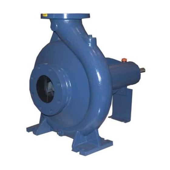
This pump is a VG Series, enclosed impeller, cen trifugal model with straight‐in suction without a suction check valve. The pump is designed for high pressure distribution of liquids containing specified entrained solids. - Page 6 VG SERIES OM-02816 SAFETY - SECTION A This information applies to VG Series containing specified entrained solids. Do not attempt to pump volatile, corro basic pumps. Gorman‐Rupp has no sive, or flammable materials which may control over or particular knowledge of damage the pump or endanger person...
- Page 7 VG SERIES OM-02816 charge hoses and piping must be re moved from the pump before lifting. Lift the pump or component only as high as necessary and keep personnel away Do not remove plates, covers, gauges, from suspended objects. pipe plugs, or fittings from an over...
-
Page 8: Installation - Section B
VG SERIES OM-02816 INSTALLATION - SECTION B Review all SAFETY information in Section A. configuration, and priming must be tailored to the specific application. Since the pressure supplied Since pump installations are seldom identical, this to the pump is critical to performance and safety,... -
Page 9: Preinstallation Inspection
OM-02816 VG SERIES PREINSTALLATION INSPECTION POSITIONING PUMP Lifting The pump assembly was inspected and tested be fore shipment from the factory. Before installation, inspect the pump for damage which may have oc curred during shipment. Check as follows: a. Inspect the pump for cracks, dents, damaged Death or serious personal injury and threads, and other obvious damage. -
Page 10: Materials
VG SERIES OM-02816 suction line should never be smaller than the pump possible. When operation involves a suction lift, the inlet. line must always slope upward to the pump from the source of the liquid being pumped; if the line... -
Page 11: Suction Line Positioning
OM-02816 VG SERIES If there is a liquid flow from an open pipe into the tance equal to at least 3 times the diameter of the sump, the flow should be kept away from the suc suction pipe. tion inlet because the inflow will carry air down into the sump, and air entering the suction line will re... -
Page 12: Alignment
VG SERIES OM-02816 If a throttling valve is desired in the discharge line, use a valve as large as the largest pipe to minimize friction losses. Never install a throttling valve in a suction line. Adjusting the alignment in one direction may alter the alignment in another direc... -
Page 13: V-Belt Drives
OM-02816 VG SERIES Check parallel adjustment by laying a straightedge Tighten the belts in accordance with the belt manu across both coupling rims at the top, bottom, and facturer's instructions. If the belts are too loose, side. When the straightedge rests evenly on both they will slip;... -
Page 14: Operation - Section C
OM-02816 VG SERIES OPERATION - SECTION C Review all SAFETY information in Section A. the priming device and pump to preserve the prime. Start the pump and open the discharge Follow the instructions on all tags, labels and de valve slowly to fill the discharge line. When installed cals attached to the pump. -
Page 15: Auxiliary Ejectors
OM-02816 VG SERIES a venturi which creates a vacuum in the pump cas Rotation ing in order to fill the suction line and pump casing The correct direction of pump rotation is counter with liquid. To prime a pump using an exhaust clockwise when facing the impeller. -
Page 16: Strainer Check
OM-02816 VG SERIES against closed valves could bring the liquid to a inches (508,0 mm) or more of mercury. If it does boil, build pressure, and cause the pump to rup not, check for air leaks in the seal, gasket, or dis... -
Page 17: Bearing Temperature Check
OM-02816 VG SERIES A sudden increase in bearing temperature is a BEARING TEMPERATURE CHECK warning that the bearings are at the point of failing to operate properly. Make certain that the bearing Bearings normally run at higher than ambient tem... -
Page 18: Troubleshooting - Section D
VG‐SERIES OM-02816 TROUBLESHOOTING - SECTION D Review all SAFETY information in Section A. Before attempting to open or service the pump: 1. Familiarize yourself with this manual. 2. Lock out or disconnect the power source to ensure that the pump will remain inoperative. - Page 19 OM-02816 VG‐SERIES TROUBLE POSSIBLE CAUSE PROBABLE REMEDY PUMP STOPS OR Discharge throttling valve partially Open discharge valve fully; check FAILS TO DELIVER closed; check that valve is installed im piping installation. RATED FLOW OR properly. PRESSURE (cont.) Pump speed too slow. Check driver output;...
-
Page 20: Preventive Maintenance
VG‐SERIES OM-02816 TROUBLE POSSIBLE CAUSE PROBABLE REMEDY BEARINGS RUN Bearing temperature is high, but Check bearing temperature regu TOO HOT within limits. larly to monitor any increase. Low or incorrect lubricant. Check for proper type and level of lubricant. Pump speed too high. Reduce speed of power source. - Page 21 OM-02816 VG‐SERIES Preventive Maintenance Schedule Service Interval* Item Daily Weekly Monthly Semi‐ Annually Annually General Condition (Temperature, Unusual Noises or Vibrations, Cracks, Leaks, Loose Hardware, Etc.) Pump Performance (Gauges, Speed, Flow) Bearing Lubrication Seal Lubrication (And Packing Adjustment, If So Equipped) V‐Belts (If So Equipped) Air Release Valve Plunger Rod (If So Equipped) Front Impeller Clearance (Wear Plate)
-
Page 22: Pump Maintenance And Repair - Section E
VG SERIES OM-02816 PUMP MAINTENANCE AND REPAIR - SECTION E MAINTENANCE AND REPAIR OF THE WEARING PARTS OF THE PUMP WILL MAINTAIN PEAK OPER ATING PERFORMANCE. STANDARD PERFORMANCE FOR PUMP MODEL VG5C3-B Based on 70 F (21 C) clear water at sea level Contact the Gorman‐Rupp Company to verify per... - Page 23 OM-02816 VG SERIES SECTION DRAWING PARTS PAGE Figure 1. Pump Model VG5C3-B PAGE E - 2 MAINTENANCE & REPAIR...
- Page 24 VG SERIES OM-02816 PARTS LIST Pump Model VG5C3-B (From S/N 1188885 up) If your pump serial number is followed by an “N”, your pump is NOT a standard production model. Contact the Gorman‐Rupp Company to verify part numbers. ITEM PART NAME...
-
Page 25: Pump And Seal Disassembly And Reassembly
OM-02816 VG SERIES PUMP AND SEAL DISASSEMBLY 5. Close the suction and discharge valves. AND REASSEMBLY 6. Vent the pump slowly and cau tiously. Review all SAFETY information in Section A. 7. Drain the pump. Follow the instructions on all tags, label and de... -
Page 26: Seal Removal
VG SERIES OM-02816 Seal Removal Remove the hardware securing the foot (35) to the base, and move the bearing housing to a clean, well‐equipped shop for disassembly. To remove the seal assembly (3), disengage the nuts (15) and slide the seal plate (6), seal cap (46),... -
Page 27: Shaft And Bearing Reassembly And Installation
OM-02816 VG SERIES foreign material. Failure to do so will great NOTE ly shorten bearing life. Do not spin dry If a hot oil bath is used to heat the bearings, both the oil and the container must be absolutely clean. If bearings. -
Page 28: Seal Reassembly And Installation
VG SERIES OM-02816 The seal is not normally reused because wear pat the bearing bore, push against the outer terns on the finished faces cannot be realigned race. Never hit the balls or ball cage. during reassembly. This could result in premature Install the inboard oil seal (42) in the bearing cover failure. -
Page 29: Impeller Installation
OM-02816 VG SERIES RETAINER BELLOWS SPRING CENTERING WASHER O‐RING SPRING STATIONARY ELEMENT SHAFT SLEEVE O‐RING IMPELLER SHAFT SEAL SEAL CAP COLLAR SETSCREW ROTATING SEAL PLATE ELEMENT Figure 2. 25271-095 Seal Assembly Slide the spring holder and spring over the sleeve and against the collar. -
Page 30: Final Pump Assembly
VG SERIES OM-02816 until both are fully seated. Install the impeller nut Bearings (48). The bearing housing was fully lubricated when Install the seal plate gasket (5). Slide the pump shipped from the factory. Check the oil level regu casing (1) over the impeller and secure it to the seal larly through the sight gauge (38) and maintain it at plate with the nuts (12). - Page 31 For U.S. and International Warranty Information, Please Visit www.grpumps.com/warranty or call: U.S.: 419-755-1280 International: +1-419-755-1352 For Canadian Warranty Information, Please Visit www.grcanada.com/warranty or call: 519-631-2870 THE GORMAN‐RUPP COMPANY D MANSFIELD, OHIO GORMAN‐RUPP OF CANADA LIMITED ST. THOMAS, ONTARIO, CANADA...
Need help?
Do you have a question about the VG Series and is the answer not in the manual?
Questions and answers