Table of Contents
Advertisement
Quick Links
OM‐05816‐01
November 1, 2005
Rev. L 03‐01‐19
INSTALLATION, OPERATION,
AND MAINTENANCE MANUAL
WITH PARTS LIST
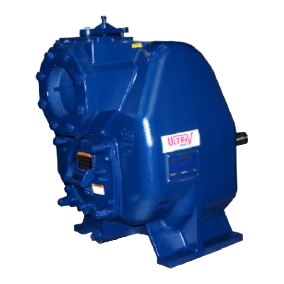
ULTRA V PUMP
MODEL
V4A60-B
INCLUDING: /WW
THE GORMAN‐RUPP COMPANY D MANSFIELD, OHIO
www.grpumps.com
D
GORMAN‐RUPP OF CANADA LIMITED
ST. THOMAS, ONTARIO, CANADA
Printed in U.S.A.
e
2005 The Gorman‐Rupp Company
Advertisement
Table of Contents

Related Manuals for GORMAN-RUPP PUMPS ULTRA V V4A60-B


Summary of Contents for GORMAN-RUPP PUMPS ULTRA V V4A60-B
- Page 1 OM‐05816‐01 November 1, 2005 Rev. L 03‐01‐19 INSTALLATION, OPERATION, AND MAINTENANCE MANUAL WITH PARTS LIST ULTRA V PUMP MODEL V4A60-B INCLUDING: /WW THE GORMAN‐RUPP COMPANY D MANSFIELD, OHIO www.grpumps.com GORMAN‐RUPP OF CANADA LIMITED ST. THOMAS, ONTARIO, CANADA Printed in U.S.A. 2005 The Gorman‐Rupp Company...
- Page 2 Register your new Gorman‐Rupp pump online at www.grpumps.com Valid serial number and e‐mail address required. RECORD YOUR PUMP MODEL AND SERIAL NUMBER Please record your pump model and serial number in the spaces provided below. Your Gorman‐Rupp distributor needs this information when you require parts or service. Pump Model: Serial Number:...
-
Page 3: Table Of Contents
TABLE OF CONTENTS INTRODUCTION ..........PAGE I - 1 SAFETY - SECTION A . - Page 4 TABLE OF CONTENTS (continued) TROUBLESHOOTING - SECTION D ......PAGE D - 1 PREVENTIVE MAINTENANCE .
-
Page 5: Introduction
ULTRA V SERIES OM-05816 INTRODUCTION Thank You for purchasing a Gorman‐Rupp pump. The following are used to alert maintenance per Read this manual carefully to learn how to safely sonnel to procedures which require special atten install and operate your pump. Failure to do so tion, to those which could damage equipment, and could result in personal injury or damage to the to those which could be dangerous to personnel:... -
Page 6: Safety - Section A
ULTRA V SERIES OM-05816 SAFETY - SECTION A This information applies to Ultra V Se containing large entrained solids or ries pumps. Gorman‐Rupp has no con slurries. Do not attempt to pump vola trol over or particular knowledge of the tile, corrosive, or flammable materials power source which will be used. - Page 7 OM-05816 ULTRA V SERIES Use lifting and moving equipment in Do not attempt to disengage any part of good repair and with adequate capacity an overheated pump unit. Vapor pres to prevent injuries to personnel or dam sure within the pump casing can eject age to equipment.
-
Page 8: Installation - Section B
ULTRA V SERIES OM-05816 INSTALLATION - SECTION B Review all SAFETY information in Section A. Check that the pump shaft rotates counter clockwise when facing the impeller. Since pump installations are seldom identical, this section offers only general recommendations and practices required to inspect, position, and ar... -
Page 9: Mounting
OM-05816 ULTRA V SERIES ing piping couplings in suction lines is not recom are not observed. Make certain that mended. hoists, chains, slings or cables are in good working condition and of suffi cient capacity and that they are posi Line Configuration tioned so that loads will be balanced Keep suction and discharge lines as straight as... -
Page 10: Strainers
ULTRA V SERIES OM-05816 stalled with the flat part of the reducers uppermost sump at a distance equal to 1 1/2 times the diame to avoid creating air pockets. Valves are not nor ter of the suction line. mally used in suction lines, but if a valve is used, install it with the stem horizontal to avoid air pock... -
Page 11: Discharge Lines
OM-05816 ULTRA V SERIES Figure 1. Recommended Minimum Suction Line Submergence vs. Velocity DISCHARGE LINES With high discharge heads, it is recommended that a throttling valve and a system check valve be in stalled in the discharge line to protect the pump from excessive shock pressure and reverse rota... -
Page 12: Automatic Air Release Valve
ULTRA V SERIES OM-05816 In low discharge head applications (less than 30 feet or 9 meters), it is recommended that the by pass line be run back to the wet well, and located 6 inches below the water level or cut‐off point of the If a manual shut‐off valve is installed in low level pump. -
Page 13: Air Release Valve Installation
OM-05816 ULTRA V SERIES Air Release Valve Installation tween the pump discharge port and the inlet side of the discharge check valve (see Figure 2). The inlet opening in the Air Release Valve is equipped with The Automatic Air Release Valve must be inde pendently mounted in a horizontal position be... -
Page 14: Coupled Drives
ULTRA V SERIES OM-05816 When mounted at the Gorman‐Rupp factory, driver and pump are aligned before shipment. Misalign ment will occur in transit and handling. Pumps must be checked and realigned before operation. Before checking alignment, tighten the foundation bolts. The pump casing feet and/or pedestal feet, and the driver mounting bolts should also be tightly secured. -
Page 15: Drive Belt Tensioning
OM-05816 ULTRA V SERIES Tighten the belts in accordance with the belt manu DRIVE BELT TENSIONING facturer's instructions. If the belts are too loose, they will slip; if the belts are too tight, there will be General Rules of Tensioning excessive power loss and possible bearing failure. -
Page 16: Operation - Section C
OM-05816 ULTRA V SERIES OPERATION - SECTION C Review all SAFETY information in Section A. Add liquid to the pump casing when: 1. The pump is being put into service for the Follow the instructions on all tags, labels and de first time. -
Page 17: Operation
OM-05816 ULTRA V SERIES If rotation is incorrect on a three‐phase motor, have pump components will deteriorate, and a qualified electrician interchange any two of the the liquid could come to a boil, build three phase wires to change direction. If rotation is pressure, and cause the pump casing to incorrect on a single‐phase motor, consult the liter... -
Page 18: Strainer Check
OM-05816 ULTRA V SERIES heated pump cautiously. It is recommended that shock waves can be transmitted to the pump and the pressure relief valve assembly be replaced at piping system. Close all connecting valves slowly. each overhaul, or any time the pump casing over heats and activates the valve. - Page 19 OM-05816 ULTRA V SERIES Checking bearing temperatures by hand is inaccu rect level (see LUBRICATION in MAINTENANCE rate. Bearing temperatures can be measured ac AND REPAIR). Bearing overheating can also be curately by placing a contact‐type thermometer caused by shaft misalignment and/or excessive vi against the housing.
- Page 20 ULTRA V SERIES OM-05816 TROUBLESHOOTING - SECTION D Review all SAFETY information in Section A. Before attempting to open or service the pump: 1. Familiarize yourself with this manual. 2. Lock out or disconnect the power source to ensure that the pump will remain inoperative.
- Page 21 OM-05816 ULTRA V SERIES TROUBLE POSSIBLE CAUSE PROBABLE REMEDY PUMP STOPS OR Strainer clogged. Check strainer and clean if neces FAILS TO DELIVER sary. RATED FLOW OR PRESSURE Suction intake not submerged at Check installation and correct sub proper level or sump too small. mergence as needed.
- Page 22 ULTRA V SERIES OM-05816 in suction and discharge gauge readings (if so PREVENTIVE MAINTENANCE equipped) between regularly scheduled inspec tions can indicate problems that can be corrected Routine preventive maintenance of the pump will before system damage or catastrophic failure oc maintain peak operating performance.
- Page 23 OM-05816 ULTRA V SERIES PUMP MAINTENANCE AND REPAIR - SECTION E MAINTENANCE AND REPAIR OF THE WEARING PARTS OF THE PUMP WILL MAINTAIN PEAK OPERATING PERFORMANCE. STANDARD PERFORMANCE FOR PUMP MODEL V4A60‐B, Including /WW Based on 70_F (21_C) clear water at sea level with Contact the Gorman‐Rupp Company to verify per...
- Page 24 OM-05816 ULTRA V SERIES PARTS PAGE SECTION DRAWING Figure 1. Pump Model V4A60-B (Including /WW) PAGE E - 2 MAINTENANCE & REPAIR...
- Page 25 OM-05816 ULTRA V SERIES PARTS LIST Pump Model V4A60-B (Including /WW) (From S/N 1333878 Up) If your pump serial number is followed by an “N”, your pump is NOT a standard production model. Contact the Gorman‐Rupp Company to verify part numbers. ITEM PART NAME PART...
- Page 26 OM-05816 ULTRA V SERIES SECTION DRAWING Î Î Ì Ì Ì Ì Ç Ç Ç Ç Ç Ç Î Î Ï Ï Ï Ï Ï Ç Ç Ç Ç Ì Ì Ì Ì Ì Î Î Ì Ì Ì Ì Ï...
- Page 27 OM-05816 ULTRA V SERIES PARTS LIST Repair Rotating Assemblies Note: Order the complete Repair Rotating Assembly from the Pump Model Assembly Parts List on page E-3. Rotating Assemblies for /WW models also include all standard parts listed below. ITEM PART PART NAME NUMBER IMPELLER...
- Page 28 OM-05816 ULTRA V SERIES to ensure that it will remain inoperative. Close all PUMP AND SEAL DISASSEMBLY valves in the suction and discharge lines. AND REASSEMBLY For power source disassembly and repair, consult Review all SAFETY information in Section A. the literature supplied with the power source, or contact your local power source representative.
- Page 29 ULTRA V SERIES OM-05816 lars (12). Install two 1/2-13 UNC x 2 inch long necessary and keep personnel away screws in the tapped holes in the back cover and from suspended objects. use them to press the back cover out of the pump casing.
- Page 30 OM-05816 ULTRA V SERIES engaged. Install the tee, and screw the handles into Turn the tee. Use caution when lifting the rotating assem Counterclockwise bly to avoid injury to personnel or damage to the assembly. Remove the O‐rings (30 and 31). Lathe Dog Arm Impeller Removal (Figure 2)
- Page 31 ULTRA V SERIES OM-05816 Clean the bearings thoroughly in fresh cleaning solvent. Dry the bearings with filtered compressed air and coat with light oil. Shaft and bearing disassembly in the field is not recommended. These operations should be performed only in a properly‐ equipped shop by qualified personnel.
- Page 32 OM-05816 ULTRA V SERIES 2. Press the oil seal into the housing until the face is Install the thrust washer (22) and secure the out just flush with the counterbored surface toward board bearing (23) to the shaft with the snap ring the inside of the housing.
- Page 33 ULTRA V SERIES OM-05816 The seal is not normally reused because wear pat precautions printed on solvent contain terns on the finished faces cannot be realigned ers. during reassembly. This could result in premature failure. If necessary to reuse an old seal in an emer Clean the seal cavity and shaft with a cloth soaked gency, carefully wash all metallic parts in fresh in fresh cleaning solvent.
- Page 34 OM-05816 ULTRA V SERIES O‐RING ENGAGED WITH SEAL PLATE BORE This seal is not designed for operation at temperatures above 160 F (71 C). Do not use at higher operating temperatures. If the seal plate was removed, install the seal plate gasket (5).
- Page 35 ULTRA V SERIES OM-05816 proper clearance as described in Impeller Instal the pipe should be slightly larger than the O.D. of lation and Adjustment. the shaft sleeve. If necessary to reuse an old seal in an emer Slide the rotating portion of the seal (consisting of gency, carefully separate the rotating and station...
- Page 36 OM-05816 ULTRA V SERIES Clean any scale or debris from the contacting sur NOTE faces in the pump casing that might interfere or Proceed with Rotating Assembly Installation be prevent a good seal with the back cover. fore installing the impeller capscrew and washer (28 and 29).
- Page 37 ULTRA V SERIES OM-05816 (13 and 14). Install the two remaining back cover PRESSURE RELIEF VALVE nuts snugly against the adjusting screws. MAINTENANCE (Figure 1) Remove the first two back cover nuts from their The back cover is equipped with a pressure relief studs.
- Page 38 OM-05816 ULTRA V SERIES ounces (3,9 liters) of SAE No. 30 non‐detergent oil tioned horizontally to provide proper drainage. to the middle of the seal level sight gauge (14) and maintain it at the middle of the gauge. Clean and Under normal conditions, drain the bearing hous...
- Page 39 For Warranty Information, Please Visit www.grpumps.com/warranty or call: U.S.: 419-755-1280 Canada: 519-631-2870 International: +1-419-755-1352 GORMAN‐RUPP PUMPS...
Need help?
Do you have a question about the ULTRA V V4A60-B and is the answer not in the manual?
Questions and answers