Table of Contents
Advertisement
Quick Links
Advertisement
Table of Contents

Subscribe to Our Youtube Channel
Related Manuals for Lord MicroStrain 3DM-CX5 Series


Summary of Contents for Lord MicroStrain 3DM-CX5 Series
- Page 1 LORD USER MANUAL 3DM-CX5-GNSS/INS GNSS-Aided Inertial Navigation System...
- Page 2 ® MicroStrain Sensing Systems 459 Hurricane Lane Williston, VT 05495 United States of America Phone: 802-862-6629 www.microstrain.com sensing_support@LORD.com sensing_sales@LORD.com Copyright © 2019 LORD Corporation Document 8500-0084 Revision B Subject to change without notice.
-
Page 3: Table Of Contents
3DM-CX5-GNSS/INS User Manual Table of Contents System Overview Sensor Overview Components Interface and Indicators Basic Setup and Operations Software Installation System Connections Software Interface 3.3.1 Interactive Help Menu Sensor Communication GNSS Satellite Link Sensor Settings 3.6.1 Saving Configurations Data Monitoring and Recording View Recorded Data Sensor Measurements Direct Sensor Measurements (IMU Outputs) - Page 4 3DM-CX5-GNSS/INS User Manual Tare Mounting Pitch-Roll Magnetometer Auto Calibration 5.3.1 Enable 5.3.2 Capture Magnetometer Manual Calibration Estimation Filter Aiding Heading Aiding Settings 5.6.1 Bias Convergence Adaptive Anomaly Rejection 5.7.1 Gravity Adaptive 5.7.2 Mag Adaptive Angular Rate and Acceleration Limits Communications Bandwidth 5.10 Platform Frame Transformation 5.11...
- Page 5 3DM-CX5-GNSS/INS User Manual 7.1.2 Sensor Direct Mode Sensor Wiring Sampling on Start-up Connecting to a Datalogger Using Wireless Adapters Troubleshooting Troubleshooting Guide Repair and Calibration Maintenance Technical Support Parts and Configurations Standard Configurations Accessories Sales Support Specifications Reference Diagrams 11.1 Sensor Dimensions and Origin 11.2 GNSS Antenna Specifications...
-
Page 6: System Overview
3DM-CX5-GNSS/INS User Manual System Overview The LORD Sensing 3DM-CX5 family of industrial-grade inertial sensors provides a wide range of triaxial inertial measurements and computed attitude and navigation solutions. In all models, the Inertial Measurement Unit (IMU) includes direct measurement of acceleration and angular rate, and some also offer atmospheric pressure readings. -
Page 7: Sensor Overview
3DM-CX5-GNSS/INS User Manual Sensor Overview The 3DM-CX5-GNSS/INS is a high-performance, industrial-grade GNSS-Aided Inertial Navigation System (GNSS/INS) that combines micro inertial sensors and a high- sensitivity embedded Global Navigation Satellite System (GNSS) receiver for use in a wide range of industrial - grade applications, such as unmanned vehicle navigation, robotic control, platform stabilization, motion tracking and analysis, vehicle health monitoring, and device aiming. -
Page 8: Components
3DM-CX5-GNSS/INS User Manual 2.1 Components The 3DM-CX5-GNSS/INS Inertial Sensor can be purchased by itself or as part of a Connectivity Kit. All software, drivers, and links to detailed documentation are included with the sensor purchase. For a complete list of available configurations, accessories, additional system products, and ordering information. -
Page 9: Interface And Indicators
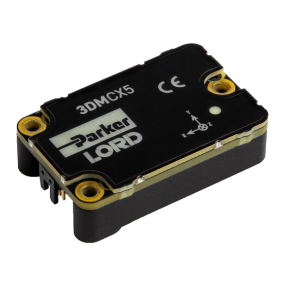
3DM-CX5-GNSS/INS User Manual 2.2 Interface and Indicators The 3DM-CX5-GNSS/INS sensor interface includes a communications and power input connector and a GNSS antenna port. The sensor is installed using the mounting and alignment holes as needed. The indicators on the 3DM-CX5-GNSS/INS include a device status indicator and the device information label. -
Page 10: Basic Setup And Operations
3DM-CX5-GNSS/INS User Manual Basic Setup and Operations Do not put the 3DM-CX5-45 in contact with, or in close proximity to, magnets. Magnets may disrupt operation and cause magnetization of internal components, which can affect magnetometer performance. If magnetization is suspected, use a degaussing tool to demagnetize. To acquire sensor measurements and computed outputs, the 3DM-CX5-GNSS/INS uses a host computer, and TTL SERIAL or USB communications port, and applicable software. -
Page 11: Software Installation
3DM-CX5-GNSS/INS User Manual 3.1 Software Installation NOTE The MIP Monitor Software Suite includes hardware drivers required for 3DM-CX5-45 sensor operation. Sensors will not be recognized without these drivers installed. To Install the MIP Monitor software on the host computer, complete the following steps: 1. -
Page 12: System Connections
3DM-CX5-GNSS/INS User Manual 3.2 System Connections Power is applied to the sensor through an external power supply, such as the one provided in the kit. Use only power supplies within the operating range of the sensor, or damage or injury could result. Once power is applied the sensor is on and active ( see Specifications on page 61 To acquire sensor data the following components are needed: 3DM-CX5-GNSS/INS sensor,... -
Page 13: Software Interface
3DM-CX5-GNSS/INS User Manual 3.3 Software Interface The MIP Monitor software includes a main window with system information and menus, a device settings window, and several data monitoring windows. The main window provides an overview of connected devices. Devices are selected by clicking on them. -
Page 14: Interactive Help Menu
3DM-CX5-GNSS/INS User Manual 3.3.1 Interactive Help Menu MIP Monitor also includes a mouse-over feature that provides explanations of the information and settings. This feature is enabled by selecting the question mark icon or Help button in any window. Figure 7. Context Sensitive Help Menu 3.4 Sensor Communication Once power has been applied to the sensor, it is functional. - Page 15 3DM-CX5-GNSS/INS User Manual Figure 8. Sensor Communication NOTE If data is not actively being exchanged between the sensor and host computer, the status message may display Not Connected. This indicates the port status, not the sensor availability. When commands are sent to the sensor, the software will automatically connect to it before sending the message.
-
Page 16: Gnss Satellite Link
3DM-CX5-GNSS/INS User Manual 3.5 GNSS Satellite Link NOTE The GNSS antenna requires unobstructed line of sight with the sky in order to achieve communication with the GNSS satellites. Communication between the GNSS receiver and GNSS satellites is initiated when the 3DM-CX5- GNSS/INS is first powered on. -
Page 17: Saving Configurations
3DM-CX5-GNSS/INS User Manual Figure 9. Device Settings Menu 3.6.1 Saving Configurations Sensor settings are saved temporarily by selecting the OK button in the Device Setup window after configuration, but they are lost when the device is powered off. To save current settings, so they are automatically restored the next time the device is powered on, select Settings >... -
Page 18: Data Monitoring And Recording
3DM-CX5-GNSS/INS User Manual 3.7 Data Monitoring and Recording Throughout the MIP Monitor views the same icons are used to control data streaming (sampling) and recording. These icons can be found in the MIP Monitor main window icon toolbar and in each data monitoring window. -
Page 19: View Recorded Data
3DM-CX5-GNSS/INS User Manual Figure 12 - Data Streaming is an example of Sensor Data Monitoring, which displays the selected IMU/AHRS measurements. In data monitoring windows, no data will be displayed until data streaming is started, and no data will be recorded (even if it is being viewed) until data recording is initiated (armed). - Page 20 3DM-CX5-GNSS/INS User Manual 1. To record data, select the Arm Recording icon at any time. 2. Select the type of data file to generate: Binary or CSV. The CSV file is the most common and can be viewed and processed by data editors such as Microsoft Excel. 3.
-
Page 21: Sensor Measurements
3DM-CX5-GNSS/INS User Manual Sensor Measurements Figure14: 3DM-CX5-GNSS/INS Block Diagram The 3DM-CX5-GNSS/INS block diagram ( ) describes its primary hardware components and internal configuration. Integrated Micro-Electro-Mechanical System (MEMS) sensors within the 3DM-CX5-GNSS/INS are collectively known as the Inertial Measurement Unit (IMU) and include tri- axial gyroscopes (gyros), tri- axial accelerometers, tri- axial magnetometers, and a pressure altimeter. -
Page 22: Direct Sensor Measurements (Imu Outputs)
3DM-CX5-GNSS/INS User Manual 4.1 Direct Sensor Measurements (IMU Outputs) The sensors in an Inertial Navigation System (INS), from which measurements for navigation and orientation are obtained, are collectively known as the Inertial Measurement Unit (IMU). These sensors are arranged on the three primary axes (x, y, and z) to sense angular rate, acceleration, and the local magnetic field. - Page 23 3DM-CX5-GNSS/INS User Manual Table 2 - IMU Measurements lists the IMU measurements available for the 3DM-CX5-GNSS/INS. Additional measurement units may be available in MIP Monitor for some outputs, however they are converted values and do not represent the actual sensor outputs. Only actual output units are listed. The Complementary Filter (CF) attitude, and up and north vector outputs are computed estimations ®...
-
Page 24: Computed Outputs
3DM-CX5-GNSS/INS User Manual 4.2 Computed Outputs (Estimation Filter) The computed outputs are measurements from the 3DM-CX5-GNSS/INS IMU sensors and GNSS receiver that are blended through an Auto- Adaptive Extended Kalman Filter (EKF) algorithm. The Kalman Filter produces a better estimation of position, velocity, and attitude (PVA) outputs than can be achieved by the inertial sensors or the GNSS individually. - Page 25 3DM-CX5-GNSS/INS User Manual Measurement Units Description indicates the current state of the EF, such Filter Status as running or initializing GNSS time corresponding to the calculated weeks & seconds GPS Time filter solution estimated position based on combined sensors degrees (position) inputs and EF, expressed in latitude, longitude, Position (LLH) meters...
-
Page 26: Sensor Reference Frames
3DM-CX5-GNSS/INS User Manual 4.3 Sensor Reference Frames 4.3.1 Geodetic Frame The World Geodetic System is the standard for cartography and navigation. The latest revision, WGS84, is the reference coordinate system for GPS, and the 3DM-CX5-GNSS/INS reports position using this coordinate frame. It also calculates the magnitude of the local gravity vector using the WGS84 reference formulas. -
Page 27: North East Down (Ned) Frame
3DM-CX5-GNSS/INS User Manual 4.3.2 North East Down (NED) Frame The North-East-Down (NED) frame is a local coordinate frame, which is formed by a tangent plane located at a particular point (current coordinates) on the WGS84 reference ellipse. The NED frame is constructed with the (true) North vector along the line of longitude, the East vector along the line Figure 18 - North East of latitude, and the Down vector normal to and towards the tangent plane (... -
Page 28: Sensor Frame
3DM-CX5-GNSS/INS User Manual 4.3.3 Sensor Frame The sensor frame is indicated on the top of the device and is oriented such that the x-axis vector is parallel with the long side of the sensor and points toward the sensor connector, the y-axis is 90° to the right of the x-axis, and the z-axis goes through the bottom of the sensor (outward). -
Page 29: Platform Frame
3DM-CX5-GNSS/INS User Manual 4.3.4 Platform Frame The 3DM-CX5-GNSS/INS includes the option to define an orientation transformation and offset distance from the sensor frame to a user-definable platform frame. This is useful when the sensor cannot be mounted in the same location or orientation as the desired reference point on the platform frame. - Page 30 3DM-CX5-GNSS/INS User Manual In the MIP Monitor software the transformation and offset settings are entered at: Settings > Device Figure > Estimation Filter > Mounting in the Mounting Offset and Mounting Transformation fields ( 21 - Platform Frame Settings see Tare Mounting Pitch-Roll on page 35 ).
-
Page 31: Performance Optimization
3DM-CX5-GNSS/INS User Manual Performance Optimization 5.1 Gyroscope Bias Gyroscope biases (offsets) can be zeroed out to set a baseline value for the static home position and conditions in the application. This should be done after sensor installation. To set the gyroscope baseline, place the sensor or sensor platform in the desired home position. Allow 2-3 minutes for the sensor to warm up and for the temperature to stabilize for the best bias capture. -
Page 32: Tare Mounting Pitch-Roll
3DM-CX5-GNSS/INS User Manual 5.2 Tare Mounting Pitch-Roll This function captures the current pitch-roll orientation of the device and sets it as the level reference, providing a convenient way to set the sensor to vehicle frame transformation. For more information on the corresponding LORD Sensing MIP Data Communications Protocol (DCP) command, see the DCP Manual. -
Page 33: Magnetometer Auto Calibration
3DM-CX5-GNSS/INS User Manual 5.3 Magnetometer Auto Calibration 5.3.1 Enable Enabling the EF Mag Hard Iron Auto Calibration allows estimation of the magnetometer bias (bias tracking) for purposes of auto- calibration. Enabling the EF Mag Soft Auto Calibration allows estimation of the magnetometer scale factor (scale factor tracking) for purposes of auto-calibration. To enable, select the sensor name in the MIP Monitor software main window, then select Settings >... -
Page 34: Capture
3DM-CX5-GNSS/INS User Manual 5.3.2 Capture This command captures the current value of the auto-calibration, applies it to the current fixed hard and soft iron calibration coefficients, and replaces the current fixed hard and soft iron calibration coefficients with the new values. This may be used in place of (or in addition to) a manual hard and see Magnetometer Manual Calibration on page 38 soft iron calibration ( ) utility such as the LORD... -
Page 35: Magnetometer Manual Calibration
3DM-CX5-GNSS/INS User Manual 5.4 Magnetometer Manual Calibration Although the 3DM-CX5-GNSS/INS magnetometers are calibrated at the factory to remove any internal magnetic influences in the device, measurements are still subject to influence from external magnetic anomalies when the sensor is installed. These anomalies are divided into two classes: hard iron offsets and soft iron distortions. - Page 36 3DM-CX5-GNSS/INS User Manual 3. The sensor should automatically appear in the sensor list. If not, use the Refresh button Figure 26 - Sensor Menu to query it and then select the sensor ( 4. Select the Arm Recording button next to Collect Data. The software will begin taking readings, as indicated by the points counter in the graphing window.
- Page 37 3DM-CX5-GNSS/INS User Manual quadrants. If the range of motion is restricted in one dimension, the Spherical Fit may be the best choice. If there are enough points in all dimensions, the Ellipsoid Fit may be better. Generally, if the Spherical and Ellipsoid Fits are close in the mean diameter, then the Ellipsoid Fit will be the best choice.
-
Page 38: Estimation Filter Aiding
3DM-CX5-GNSS/INS User Manual 5.5 Estimation Filter Aiding There are four primary categories with sub-menus in each to customize GNSS,heading , pitch-roll, and altitude . To enter the Estimation Filter Aiding menu, select the sensor name in the MIP Monitor software main window, then select Settings > Device > Estimation Filter > EF Aiding. 1. -
Page 39: Heading Aiding Settings
3DM-CX5-GNSS/INS User Manual 5.6 Heading Aiding Settings Device settings are stored in the sensor memory. Only the configuration options that are available for the type of sensor being used are displayed in the configurations menus. The 3DM-CX5-GNSS/INS has eight heading options. If the setting is an external reference, the user has to provide a heading reference (for example, GPS External Receiver on page 1 ). -
Page 40: Bias Convergence
3DM-CX5-GNSS/INS User Manual 5.6.1 Bias Convergence Accurate estimation of the biases can take several minutes to converge, therefore after the filter is initialized, the free-inertial performance will continue to improve until the bias estimations settles. The MEMS sensor manufacturers quote bias drift stability numbers which correspond to the expected drift in bias while the sensor is operating. -
Page 41: Mag Adaptive
3DM-CX5-GNSS/INS User Manual 5.7.2 Mag Adaptive Enabling this feature will allow the filter to reject magnetometer readings when the magnitude error exceeds the high limit (in m/s ^ 2). The bandwidth (in Hz) sets the cutoff frequency of the low pass see Communications Bandwidth on page 45 filter applied to the magnetometer error ( ). -
Page 42: Angular Rate And Acceleration Limits
3DM-CX5-GNSS/INS User Manual Angular Rate and Acceleration Limits The 3DM-CX5-GNSS/INS angular rate and acceleration ranges depend on the sensors installed in the device. Exceeding the specified range for either sensor will result in estimated state errors and elevated uncertainties until the over-range event is corrected and the filter can resolve the errors. Communications Bandwidth When selecting sensor and estimation outputs to be recorded, communication bandwidth considerations should be taken into account, especially when using RS232 serial communications. - Page 43 3DM-CX5-GNSS/INS User Manual must be at an angle with the oncoming air to generate lift. Making the assumption that the two values are the same and using the pitch angle as an input to an autopilot is a mistake. In order to obtain the attitude of the vehicle, something more is needed.
-
Page 44: Estimation Filter Convergence
3DM-CX5-GNSS/INS User Manual The 3DM-CX5-GNSS/INS has a full-state dynamics model. The state propagation utilizes Newton’s and Euler’s equations of motion with the acceleration and angular rate treated as control inputs. In addition to the GNSS measurement, the IMU magnetometer is available to correct heading mis- alignments which occur during periods of low dynamics. -
Page 45: Output Uncertainty
3DM-CX5-GNSS/INS User Manual 5.12.2 Output Uncertainty The 3DM-CX5-GNSS/INS estimation data set includes a filter status field that contains a set of status flags. These flags pertain to high covariance values for position, velocity, attitude, and inertial sensor parameters. These flags should be monitored and cross- checked against the corresponding uncertainty fields when they appear. - Page 46 3DM-CX5-GNSS/INS User Manual To export the sensor settings, select the sensor name in the MIP Monitor software main window, then select Settings > Export Settings, then follow the prompt to choose where the file will be saved, and select OK. The file will be named by default using the sensor name, serial number, date and time. Figure 33.
-
Page 47: Sensor Installation
3DM-CX5-GNSS/INS User Manual Sensor Installation 6.1 Sensor Mounting The 3DM-CX5-GNSS/INSsensor housing is rated for indoor use only, unless used inside a protective enclosure. When using the internal GNSS receiver, the GNSS antenna connector on the side of the sensor must be accessible. The connector and cable must be non- magnetic. The MMCX to SMA adapter cable supplied with all 3DM-CX5-GNSS/INS is non-magnetic. -
Page 48: Oem System Integration
3DM-CX5-GNSS/INS User Manual OEM System Integration The 3DM-CX5-GNSS/INS connectivity kit comes with everything that is needed for sensor configuration, operation, and data collection. However, many applications will require custom solutions because of physical or environmental constraints, required sensor output processing, or for integration into control See Sales Support on page 65 systems that react to the sensor outputs. -
Page 49: Packet Builder
3DM-CX5-GNSS/INS User Manual 7.1.1 Packet Builder To expedite program development, a packet builder tool is included in the MIP Monitor software. The packet builder allows users to send multiple packets to the 3DM-CX5-GNSS/INS and view the resulting reply data. Applicable protocol structure and design is described in the 3DM-CX5-GNSS/INS LORD Sensing MIP Data Communications Protocol (DCP) Manual DCP Manual. - Page 50 3DM-CX5-GNSS/INS User Manual To enter this mode select Advanced > Communications> Sensor Direct from the MIP Monitor main Figure 36 - window. Once in this mode the device status message will indicate Sensor Direct Mode ( Sensor Direct Mode To exit Sensor Direct Mode select the Refresh button in the MIP Monitor at any time, or use Advanced >...
-
Page 51: Sensor Wiring
3DM-CX5-GNSS/INS User Manual 7.2 Sensor Wiring Only use power supplies within the operating range of the sensor, or permanent sensor damage or personal injury could result. There are two input power pins available, each with different voltage ranges. Connect only one at a time. Observe connection polarity. -
Page 52: Sampling On Start-Up
3DM-CX5-GNSS/INS User Manual 7.3 Sampling on Start-up The Save Current Settings command can be used to instruct the sensor to start streaming data as soon as it powered on. This can be useful in sensor integration applications in which immediate data acquisition is desired, and connection to MIP Monitor for data logging is not required. -
Page 53: Connecting To A Datalogger
3DM-CX5-GNSS/INS User Manual 7.4 Connecting to a Datalogger Many inertial applications incorporate dataloggers of all different types to collect and distribute sensor outputs. For more information and examples refer to the "Using Dataloggers with Inertial Sensors" Technical Note on the LORD Sensing website, or contact LORD Sensing Technical Support ( Technical Support on page 62 7.5 Using Wireless Adapters In some applications it can be very useful to set up wireless communications between the sensor to the... -
Page 54: Troubleshooting
3DM-CX5-GNSS/INS User Manual Troubleshooting 8.1 Troubleshooting Guide... - Page 55 3DM-CX5-GNSS/INS User Manual Problem Possible cause and recommended solution 1.1 no power is applied The status indicator on the device will be off. Verify the sensor 1. POWER is connected to a power source and the status indicator illuminates. sensor does not power on 1.2 power source is off or mis-wired Verify the device power source is connected correctly.
- Page 56 3DM-CX5-GNSS/INS User Manual Problem Possible cause and recommended solution Sensing for reconfiguration. 2.5 GNSS receiver is not communicating The GNSS antenna requires unobstructed line of sight to the sky in order to link with the GNSS satellites. Also verify the GNSS antenna is plugged into the sensor and the cable is intact.
- Page 57 3DM-CX5-GNSS/INS User Manual Problem Possible cause and recommended solution the LORD Sensing MIP Data Communications Protocol (DCP) to make it readable. 3.6 sensor has been magnetized Contact or close proximity with magnets may disrupt the sensor operation and cause magnetization of internal components, which can affect magnetometer performance.
-
Page 58: Repair And Calibration
3DM-CX5-GNSS/INS User Manual 8.2 Repair and Calibration General Instructions In order to return any LORD Sensing product, you must contact LORD Sensing Sales or Technical Support to obtain a Return Merchandise Authorization (RMA) number. All returned merchandise must be in the original packaging, including manuals, accessories, cables, etc. -
Page 59: Technical Support
3DM-CX5-GNSS/INS User Manual 8.4 Technical Support There are many resources for product support found on the LORD Sensing website including technical notes, FAQs, and product manuals. http://www.microstrain.com/support_overview.aspx For further assistance our technical support engineers are available to help with technical and applications questions. -
Page 60: Parts And Configurations
3DM-CX5-GNSS/INS User Manual Parts and Configurations 9.1 Standard Configurations For the most current product information, custom, and OEM options not listed below, refer to the LORD Sensing website or contact the LORD Sensing Sales Department. Table 4 - Model Numbers describes the standard models available at the time this manual was published. - Page 61 3DM-CX5-GNSS/INS User Manual The same options are available in each model, and are indicated in the last four digits of the product see Components on page 1 part number. For a list of the starter kit contents,( Figure 39. Standard Part Numbers...
-
Page 62: Accessories
3DM-CX5-GNSS/INS User Manual Accessories The following parts are available for use with the 3DM-CX5-GNSS/INS. For the most current product see Sales Support information refer to the LORD Sensing website or contact the Sales Department. ( on page 65 Description LORD Sensing Part Number 6212-3010 RS232 connectivity kit 6212-3009... -
Page 63: Specifications
3DM-CX5-GNSS/INS User Manual Specifications See Datasheet for Specifications: https://www.microstrain.com/inertial-sensors/3DM-CX5-GNSS/INS... -
Page 64: Reference Diagrams
3DM-CX5-GNSS/INS User Manual Reference Diagrams The diagrams in this section are to intended to aid in product installation and troubleshooting. For more see Technical Support on page 62 information contact LORD Sensing Technical Support ( 11.1 Sensor Dimensions and Origin This diagram describes the sensor physical specification including the measurement point of origin. -
Page 65: Gnss Antenna Specifications
3DM-CX5-GNSS/INS User Manual 11.2 GNSS Antenna Specifications These specifications describe the GNSS antenna included in the 3DM-CX5-GNSS/INS connectivity kit, as well as the short sensor to SMA coax jumper. -
Page 66: Power Supply Specifications (Rs232 Kits Only)
3DM-CX5-GNSS/INS User Manual 11.3 Power Supply Specifications (RS232 kits only) The power supply is only required for the RS232 devices. These specifications describe the power supply included in the 3DM-CX5-GNSS/INS connectivity kit. -
Page 67: Communication And Power Cables
3DM-CX5-GNSS/INS User Manual 11.4 Communication and Power Cables These diagrams describe the cables included in the 3DM-CX5-GNSS/INS connectivity kits. Only one is included in each kit, depending on the type of kit ordered. Figure 41. RS232 Communications and power cable Figure 42. - Page 68 3DM-CX5-GNSS/INS User Manual This breakout cable enables users to wire from MicroStrain’s standard connector to their own equipment. Pin # Signal Color D- usb Black D+ usb Brown RX rs232 Orange TX rs232 Yellow Green Blue Violet Grey Figure 43. Connecter breakout/interface cable (sold separately, PN: 6224-0100)
-
Page 69: Reference Documents
3DM-CX5-GNSS/INS User Manual Reference Documents Many references are available on the LORD Sensing website including product user manuals, technical notes, and quick start guides. These documents are continuously updated and may provide more accurate information than printed or file copies. Document Where to find it 3DM-CX5-GNSS/INS...
Need help?
Do you have a question about the 3DM-CX5 Series and is the answer not in the manual?
Questions and answers