Table of Contents
Advertisement
Quick Links
Advertisement
Table of Contents

Related Manuals for Lord MicroStrain 3DM-CV5-15


Summary of Contents for Lord MicroStrain 3DM-CV5-15
- Page 1 LORD USER MANUAL ® -CV5-15 Vertical Reference Unit (VRU)
- Page 2 , DVRT , EmbedSense , FAS-A , G-Link ® ® ™ ® ® ® ® Little Sensors, Big Ideas. , LORD Microstrain , Live Connect , LXRS , MathEngine , MicroStrain , MXRS , Node ® ™ ® ® ®...
-
Page 3: Table Of Contents
® -CV5-15 User Manual Table of Contents System Family Overview Sensor Overview 2.1 Components 2.2 Interface and Indicators Basic Setup and Operations 3.1 Software Installation 3.2 System Connections 3.3 Software Interface 3.3.1 Interactive Help Menu 3.4 Sensor Communication 3.5 Sensor Settings 3.5.1 Saving Configurations 3.6 Data Monitoring and Recording 3.7 View Recorded Data... - Page 4 ® -CV5-15 User Manual 5.3.1 Bias Convergence 5.4 Adaptive Anomaly Rejection 5.4.1 Gravity Adaptive 5.5 Angular Rate and Acceleration Limits 5.6 Communications Bandwidth 5.7 Estimation Filter Operation 5.8 Estimation Filter Convergence 5.8.1 Initial Convergence 5.8.2 Output Uncertainty 5.9 Vibration Isolation 5.10 IMU Sensor Calibration 5.11 Temperature Compensation 5.12 Import and Export Settings...
- Page 5 ® -CV5-15 User Manual 8.4 Maintenance Parts and Configurations 9.1 Standard Configurations 9.2 Accessories 9.3 Sales Support Specifications 11.1 3DM-CV5 Sensors 11.2 3DM-CV5 Development Kit Reference Documents Safety Information 12.1 Disposal and Recycling Glossary...
-
Page 6: System Family Overview
® -CV5-15 User Manual System Family Overview The LORD Sensing 3DM-CV5 family of industrial-grade, board-level inertial sensors provides a wide range of triaxial inertial measurements and computed attitude and navigation solutions. In all models, the Inertial Measurement Unit (IMU) includes direct measurement of acceleration and angular rate, and some also offer atmospheric pressure readings. -
Page 7: Sensor Overview
The combination of sensors, environmental compensation, and dual on- board processing with an Auto-Adaptive Extended Kalman Filter (EKF) allows the 3DM-CV5-15 to perform well in a wide variety of applications that require low noise, drift, gain, and offset errors. -
Page 8: Components
User Manual 2.1 Components The 3DM-CV5-15 Inertial Sensor can be purchased by itself or as part of a Development Kit. All software, drivers, and links to detailed documentation are included with the sensor purchase. For a complete list of available configurations, accessories, additional system products, and ordering... -
Page 9: Interface And Indicators
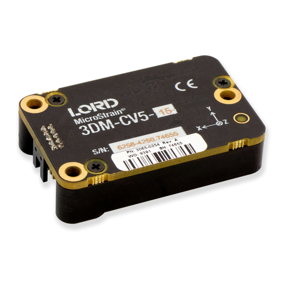
( see Sensor Mounting on page 36 The indicators on the 3DM-CV5-15 include a device status indicator and the device information label. The table below describes the basic status indicator behavior. The device information label includes the... -
Page 10: Basic Setup And Operations
User Manual Basic Setup and Operations To acquire sensor measurements and computed outputs, the 3DM-CV5-15 uses a host computer,an RS232 or USB communications port, and applicable software. The LORD Sensing MIP Monitor software is provided with the system and includes all functions needed for sensor configuration and data acquisition. -
Page 11: Software Installation
User Manual 3.1 Software Installation NOTE The MIP Monitor Software Suite includes hardware drivers required for 3DM-CV5-15 sensor operation. Sensors will not be recognized without these drivers installed. To Install the MIP Monitor software on the host computer, complete the following steps: 1. -
Page 12: System Connections
( see Specifications on page 1 To acquire sensor data the following components are needed: 3DM-CV5-15 sensor, communication cable, power cable (as applicable for RS232 communications) , connectivity board, and a host computer with LORD Sensing MIP Monitor installed. -
Page 13: Interactive Help Menu
® -CV5-15 User Manual Figure 6 - Main Window Display 3.3.1 Interactive Help Menu MIP Monitor also includes a mouse-over feature that provides explanations of the information and settings. This feature is enabled by selecting the question mark icon or Help button in any window. Figure 7 - Context Sensitive Help Menu 3.4 Sensor Communication Once power has been applied to the sensor, it is functional. - Page 14 ® -CV5-15 User Manual 3. The sensor should appear in the device list automatically when the software is running. The list includes the device information and communication port assignment. If the sensor is not automatically discovered, use the refresh button. Figure 8 -Sensor Communication NOTE If data is not actively being exchanged between the sensor and host computer, the status...
-
Page 15: Sensor Settings
Device Settings, or select Settings > Device from the main menu. a. Main menu tabs: The main tabs divide the settings into functional groups for the available measurements. For the 3DM-CV5-15 these include b. Message Format (first sub-menu tab): Under each main menu tab there are additional sub- menu tabs, including the Message Format tab, which allows the user to select the meas- urement type to be displayed and recorded (b1) and the data rate in samples/second(b2). -
Page 16: Saving Configurations
® -CV5-15 User Manual 3.5.1 Saving Configurations Sensor settings are saved temporarily by selecting the OK button in the Device Setup window after configuration, but they are lost when the device is powered off. To save current settings, so they are automatically restored the next time the device is powered on, select Settings >... -
Page 17: Data Monitoring And Recording
® -CV5-15 User Manual 3.6 Data Monitoring and Recording Throughout the MIP Monitor views the same icons are used to control data streaming (sampling) and recording. These icons can be found in the MIP Monitor main window icon toolbar and in each data monitoring window. -
Page 18: View Recorded Data
® -CV5-15 User Manual Figure 12 -Data Streaming 3.7 View Recorded Data Recorded data is stored in either Binary (.bin) or Comma Separated Values (.csv) format, depending on what was selected at the initiation of data recording. The files can be found in the directory specified at that time or in the default directory on the host computer desktop. - Page 19 ® -CV5-15 User Manual Data recorded in Binary format requires a translation program utilizing the LORD Sensing MIP Data Communications Protocol (DCP) to make it user-readable. 1. To record data, select the Arm Recording icon at any time. 2. Select the type of data file to generate: Binary or CSV. The CSV file is the most common and can be viewed and processed by data editors such as Microsoft Excel.
- Page 20 ® -CV5-15 User Manual 5. Select the Stop Streaming icon to end sampling. 6. Use the red "X" in the upper right of the sensor monitoring window to exit monitoring mode.
-
Page 21: Sensor Measurements
Computed estimations for attitude, acceleration, angular rate, and heading are available outputs on the 3DM-CV5-15. To achieve these estimations, the MEMS sensors are processed by an IMU Estimation Filter (EF) microprocessor with an Adaptive Kalman Filter (AKF) . Additional user settings such as measurement filtering, biasing, and tolerance values offer adjustments for specific applications. -
Page 22: Direct Sensor Measurements (Imu Outputs)
® -CV5-15 User Manual 4.1 Direct Sensor Measurements (IMU Outputs) The sensors in an Inertial Navigation System (INS), from which measurements for navigation and orientation are obtained, are collectively known as the Inertial Measurement Unit (IMU). These sensors are arranged on the three primary axes (x, y, and z) to sense angular rate acceleration. The gyroscopes are used to adjust the current attitude estimate when an angular rate is sensed. -
Page 23: Computed Outputs
User Manual Table 2 - IMU Measurements lists the IMU measurements available for the 3DM-CV5-15. Additional measurement units may be available in MIP Monitor for some outputs, however they are converted values and do not represent the actual sensor outputs. Only actual output units are listed. - Page 24 ® -CV5-15 User Manual Figure 16 -Estimation Filter Settings All of the estimation filter outputs are available to record and most, but not all, are available to view in real time in MIP Monitor. In addition to the standard solution, additional filter outputs, such as uncertainties, inertial sensor bias and scale factors, filter status, and physical models (WGS84, WMM, Table 3 - Estimation Filter Outputs and SAM) are available (...
- Page 25 ® -CV5-15 User Manual To view and record Estimation outputs, see Basic Setup and Operations on page 10 Measurement Units Description indicates the current state of the EF, such Filter Status as running or initializing time corresponding to the calculated filter GPS Time weeks &...
-
Page 26: Sensor Reference Frames
® -CV5-15 User Manual 4.3 Sensor Reference Frames 4.3.1 Geodetic Frame The World Geodetic System is the standard for cartography and navigation. The latest revision, WGS84, is the reference coordinate system for GPS It also calculates the magnitude of the local gravity vector using the WGS84 reference formulas. -
Page 27: North East Down (Ned) Frame
For most applications, this assumption is valid and provides a more intuitive reference frame for expressing attitude information than a global frame. The 3DM-CV5-15 reports velocity in this frame and attitude with respect to this frame. Figure 18 -... -
Page 28: Sensor Frame
The view can be rotated for clicking, holding, and dragging the image. Refer to the 3DM-CV5-15 dimensional diagram for the location of the measurement origin ( Reference Diagrams on page 1... -
Page 29: Performance Optimization
® -CV5-15 User Manual Performance Optimization 5.1 Gyroscope Bias Gyroscope biases (offsets) can be zeroed out to set a baseline value for the static home position and conditions in the application. This should be done after sensor installation. To set the gyroscope baseline, place the sensor or sensor platform in the desired home position. Allow 2-3 minutes for the sensor to warm up and for the temperature to stabilize for the best bias capture. -
Page 30: Estimation Filter Aiding
® -CV5-15 User Manual 5.2 Estimation Filter Aiding There are categories to customize heading pitch-roll. To enter the Estimation Filter Aiding menu, select the sensor name in the MIP Monitor software main window, then select Settings > Device > Estimation Filter > EF Aiding. 1. -
Page 31: Heading Aiding Settings
® -CV5-15 User Manual 5.3 Heading Aiding Settings Device settings are stored in the sensor memory. Only the configuration options that are available for the type of sensor being used are displayed in the configurations menus. The 3DM- CV5- 15 has heading options. -
Page 32: Bias Convergence
® -CV5-15 User Manual 5.3.1 Bias Convergence Accurate estimation of the biases can take several minutes to converge, therefore after the filter is initialized, the free-inertial performance will continue to improve until the bias estimations settles. The MEMS sensor manufacturers quote bias drift stability numbers which correspond to the expected drift in bias while the sensor is operating. -
Page 33: Angular Rate And Acceleration Limits
-CV5-15 User Manual 5.5 Angular Rate and Acceleration Limits The 3DM-CV5-15 angular rate and acceleration ranges depend on the sensors installed in the device. Exceeding the specified range for either sensor will result in . 5.6 Communications Bandwidth When selecting sensor and estimation outputs to be recorded, communication bandwidth considerations should be taken into account, especially when using RS232 serial communications. -
Page 34: Output Uncertainty
5.8.2 Output Uncertainty The 3DM-CV5-15 estimation data set includes a filter status field that contains a set of status flags. These flags pertain to high covariance values for attitude and inertial sensor parameters. These flags should be monitored and cross-checked against the corresponding uncertainty fields when they appear. - Page 35 ® -CV5-15 User Manual To import the sensor settings, select the sensor name in the MIP Monitor software main window, then select Settings > Import Settings, then follow the prompt to choose where the file will be saved and name the file. To export the sensor settings, select the sensor name in the MIP Monitor software main window, then select Settings >...
-
Page 36: Sensor Installation
® -CV5-15 User Manual Sensor Installation 6.1 Sensor Mounting See the CV5 Interface Control Document for detailed drawings and mounting instructions. The sensor has three holes for fastening to ensure maximum stability. Mounting fasteners should be 2- 56 x ½" button head screws, either brass or 300 series stainless steel. The sensor can be mounted in any orientation, as required for the application. -
Page 37: System Integration
For these applications the 3DM-CV5-15 is available as a stand- alone component with optional interface connectors. The communication protocol used for configuring See Sales and acquiring sensor data and estimations outputs is available for these applications as well. -
Page 38: Packet Builder
7.1.1 Packet Builder To expedite program development, a packet builder tool is included in the MIP Monitor software. The packet builder allows users to send multiple packets to the 3DM-CV5-15 and view the resulting reply data. Applicable protocol structure and design is described in the 3DM-CV5-15 LORD Sensing MIP Data Communications Protocol (DCP) Manual DCP Manual . - Page 39 ® -CV5-15 User Manual To enter this mode select Advanced > Communications> Sensor Direct from the MIP Monitor main Figure 27 - window. Once in this mode the device status message will indicate Sensor Direct Mode ( Sensor Direct Mode To exit Sensor Direct Mode select the Refresh button in the MIP Monitor at any time, or use Advanced >...
-
Page 40: Sensor Wiring
Logic Level GPIO Logic Level Disable Disable (Open or Low = Enable) Mounting Holes Chassis Chassis Ground * USB is not available on the 3DM-CV5-15 and may be left connected to USB or unconnected. Figure 28 -Pin Locations and Functions... -
Page 41: Sampling On Start-Up
® -CV5-15 User Manual 7.3 Sampling on Start-up The Save Current Settings command can be used to instruct the sensor to start streaming data as soon as it powered on. This can be useful in sensor integration applications in which immediate data acquisition is desired, and connection to MIP Monitor for data logging is not required. -
Page 42: Connecting To A Datalogger
® -CV5-15 User Manual 7.4 Connecting to a Datalogger Many inertial applications incorporate dataloggers of all different types to collect and distribute sensor outputs. For more information and examples refer to the "Using Dataloggers with Inertial Sensors" Technical Note on the LORD Sensing website, or contact LORD Sensing Technical Support ( Technical Support on page 46 7.5 Using Wireless Adapters In some applications it can be very useful to set up wireless communications between the sensor to the... -
Page 43: Troubleshooting
® -CV5-15 User Manual Troubleshooting 8.1 Troubleshooting Guide Problem Possible cause and recommended solution 1.1 no power is applied Make sure the sensor is connected to a power source. 1. POWER 1.2 power source is off or miswired sensor does not power Verify the device power source is connected correctly. - Page 44 ® -CV5-15 User Manual Problem Possible cause and recommended solution could result in permanent damage or cause it to not work properly. 1.4 sensor is in firmware update mode Firmware update mode is used when updating firmware on the device. If the firmware updater fails, it is possible that the device can get stuck in the firmware update mode, and the sensor will be non-responsive.
- Page 45 ® -CV5-15 User Manual Problem Possible cause and recommended solution 3. DATA ACQUISITION or recorded, enter the Device Settings menu and verify the sampling settings. sensor data is missing 3.2 streaming has not started or incorrect In MIP Monitor the device status information field will indicate Streaming.
-
Page 46: Repair And Calibration
® -CV5-15 User Manual 8.2 Repair and Calibration General Instructions In order to return any LORD Sensing product, you must contact LORD Sensing Sales or Technical Support to obtain a Return Merchandise Authorization (RMA) number. All returned merchandise must be in the original packaging, including manuals, accessories, cables, etc. -
Page 47: Maintenance
® -CV5-15 User Manual For further assistance our technical support engineers are available to help with technical and applications questions. Technical Support sensing_support@LORD.com Phone: 802-862-6629 SKYPE: microstrain.orientation.support Live Chat is available from the website during business hours: 9:00 AM to 5:00 PM (Eastern Time US & Canada) 8.4 Maintenance There are no user- serviceable parts on the 3DM - CV5 - 15. -
Page 48: Parts And Configurations
® -CV5-15 User Manual Parts and Configurations 9.1 Standard Configurations For the most current product information, custom, and OEM options not listed below, refer to the LORD Sensing website or contact the LORD Sensing Sales Department. Table 4 - Model Numbers describes the standard models available at the time this manual was published. - Page 49 ® -CV5-15 User Manual The same options are available in each model, and are indicated in the last four digits of the product part number. For a list of the starter kit contents,( see Components on page 1 Figure 30 -Standard Part Numbers...
-
Page 50: Accessories
® -CV5-15 User Manual Accessories The following parts are available for use with the 3DM - CV5 - 15. For the most current product information refer to the LORD Sensing website or contact the Sales Department. ( see Sales Support on page 50 ). -
Page 51: Specifications
® -CV5-15 User Manual Specifications Specifications General Triaxial accelerometer, triaxial gyroscope, temperature Integrated sensors sensors, and pressure altimeter Inertial Measurement Unit (IMU) outputs: acceleration, angular rate, ambient pressure, delta theta, delta velocity Computed outputs: Extended Kalman Filter (EKF):filter status, attitude Data outputs estimates (Euler angles, quaternion, orientation matrix), bias compensated angular rate, pressure... - Page 52 ® -CV5-15 User Manual Computed Outputs EKF outputs: ±0.5° RMS roll and pitch (typ) Attitude accuracy CF outputs: ±0.8° RMS roll & pitch (typ) Attitude heading range 360° about all axes Attitude resolution 0.05° Attitude repeatability 0.2° (typ) Calculation update rate 500 Hz Computed data output EKF outputs: 1 Hz to 500 Hz...
-
Page 53: 3Dm-Cv5 Sensors
® -CV5-15 User Manual 11.1 3DM-CV5 Sensors See the CV5 Interface Control Document for detailed diagrams, notes and references on the 3DM- CV5 family of inertial sensors. Figure 31 -3DM-CV5 Sensor... -
Page 54: 3Dm-Cv5 Development Kit
® -CV5-15 User Manual 11.2 3DM-CV5 Development Kit See the 3DM- CV5 Reference Design Documentation for detailed drawings and notes on the components included in the development kit. Figure 32 -C-Series Connectivity Board... -
Page 55: Reference Documents
Many references are available on the LORD Sensing website including product user manuals, technical notes, and quick start guides. These documents are continuously updated and may provide more accurate information than printed or file copies. Document Where to find it 3DM-CV5-15 http://www.microstrain.com/documents/inertial support documentation NIST Calibration Procedures http://www.nist.gov/calibrations/ http://www.astm.org/Standard/standards-and-... -
Page 56: Safety Information
May be used to indicate important operational conditions. 12.1 Disposal and Recycling The 3DM-CV5-15 contains internal printed circuit boards and electronic components. These items are known to contain toxic chemicals and heavy metals that are harmful to humans health and the environment. ... -
Page 57: Glossary
® -CV5-15 User Manual Glossary A/D Value The digital representation of analog voltages in an analog-to-digital (A/D) conversion. The accuracy of the conversion is dependent on the resolution of the system electronics. Higher resolution produces a more accurate conversion. Acceleration In physics,acceleration is the change in the rate of speed (velocity) of an object over time. - Page 58 ® -CV5-15 User Manual ASTM (Association of Standards and Testing) a nationally accepted organization for the testing and calibration of technological devices Attitude the orientaion of an object in space with reference to a defined frame, such as the North-East-Down (NED) frame Azimuth A horizontal arc measured between a fixed point (such as true north) and the vertical circle passing...
- Page 59 ® -CV5-15 User Manual Delta-Theta the time integral of angular rate expressed with refernce to the device local coordinate system, in units of radians Delta-velocity the time integral of velocity expressed with refernce to the device local coordinate system, in units of g*second where g is the standard gravitational constant ECEF (Earth Centered Earth Fixed) a reference frame that is fixed to the earth at the center of the earth and turning about earth's axis in the...
- Page 60 ® -CV5-15 User Manual Host (computer) The host computer is the computer that orchestrates command and control of attached devices or net- works. Inertial Measurement System Inclinometer device used to measure tilt, or tilt and roll Inertial pertaining to systems that have inertia or are used to measure changes in inertia as in angular or linear accelerations INS (Inertial Navigation System) systems that use inertial measurements exclusively to determine position, velocity, and attitude, given...
- Page 61 ® -CV5-15 User Manual NED (North-East-Down) A geographic reference system acronym for Original Equipment Manufacturer Offset A non-zero output signal of a sensor when no load is applied to it, typically due to sensor imperfections. Also called bias. Orientation The orientaion of an object in space with reference to a defined frame. Also called attitude. Pitch In navigation pitch is what occurs when vertical force is applied at a distance forward or aft from the cen- ter of gravity of the platform, causing it to move up or down with respect to the sensor or platform frame...
- Page 62 ® -CV5-15 User Manual Roll In navigation roll is what occurs when a horizontal force is applied at a distance right or left from the cen- ter of gravity of the platform, causing it to move side to side with respect to the sensor or platform frame origin.
- Page 63 ® -CV5-15 User Manual Vector a measurement with direction and magnitude with refernce from one point in space to another Velocity The rate of change of position with respect to time. Also called speed. WAAS (Wide Area Augmentation System) An air navigation aid developed to allow aircraft to rely on GPS for all phases of flight, including pre- cision approaches to any airport.
Need help?
Do you have a question about the 3DM-CV5-15 and is the answer not in the manual?
Questions and answers