Advertisement
LORD TECHNICAL NOTE
SG-Link
350 Ohm Tester Board
Overview
The 350 Ohm Tester Board (part number 6309-6000) provides a precise instrument to test
the differential input channel and the single ended input channel of the SG-Link
can be used with any SG-Link
bridge or ½ bridge with 350 ohm completion. The Tester Board is used in conjunction with
®
Node Commander
software.
Hardware Installation
Determine the bridge configuration of the SG-Link
accompanying certificates and documentation.
Set the appropriate dip switch settings for the bridge configuration using the guide
(bottom of the Tester Board). For our example we will use a FULL bridge
configuration.
Set switches 1, 2 and 3 to ON and switch 4 to OFF. As you view
Figure 2, switches 1, 2 and 3 would be to the left and switch 4 would
be to the right.
Note: The dip switches may come with a brown protective film over
their surface; simply peel the film off to access the white levers.
Turn the SG-Link
charger barrel connector to insure the internal battery is not being
charged.
Loosen (by turning counterclockwise) the 8 terminal screws in the
green Phoenix connector on the SG-Link
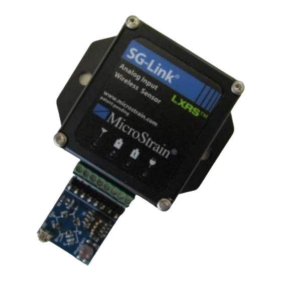
Insert the 8 fingers of the Tester Board into the Phoenix connector
as shown in Figure 1.
Tighten snuggly (but do not over-tighten) the 8 terminal screws.
Turn the SG-Link
Software Operation
Launch Node Commander
Right-click the node and a drop-down menu will appear.
Click Configure.
Click Configure Node and the Configuration window will appear.
Click the Channels tab.
Enable channels 1 and 4 by checking the checkboxes.
Click Apply.
Click the Configure button for channel 1.
The Configuration (Channel 1) window will appear.
Set the Hardware Gain to 503.
Set the Auto-Balance radio button to Midscale.
Click the Auto-Balance button.
An auto-balance will occur and a confirming message will appear.
Click OK.
Set the Conversion Coefficients to Strain and μStrain will automatically fill in as Units.
1
®
-LXRS
®
®
-LXRS
that has its differential input channel outfitted as full
®
®
-LXRS
power switch off and unplug the battery
®
®
®
-LXRS
power switch on.
®
software and establish communications with the SG-Link
®
®
®
-LXRS
®
-LXRS
.
®
®
-LXRS
. It
by reviewing its
Figure 1: Tester Board
Figure 2: Dip Switches
®
-LXRS
®
as normal.
Advertisement
Table of Contents

Related Manuals for Lord MicroStrain SG-Link-LXRS


Summary of Contents for Lord MicroStrain SG-Link-LXRS
- Page 1 LORD TECHNICAL NOTE ® ® SG-Link -LXRS 350 Ohm Tester Board Overview The 350 Ohm Tester Board (part number 6309-6000) provides a precise instrument to test ® ® the differential input channel and the single ended input channel of the SG-Link -LXRS .
- Page 2 ® ® SG-Link -LXRS 350 Ohm Tester Board Click the Strain Wizard button. The Strain Wizard window will appear Set the Bridge Type to Full Bridge. Click Next to move to the next view. Click Use Strain Measurement Wizard. ...
- Page 3 These are the default settings. This will remove the Tester Board’s configuration and allow you to start fresh with your own sensors. Support ® LORD MicroStrain support engineers are always available to expand on this subject and support you in any way we can. Copyright © 2013 LORD Corporation LORD Corporation ®...
Need help?
Do you have a question about the SG-Link-LXRS and is the answer not in the manual?
Questions and answers