Advertisement
Quick Links
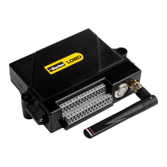
LORD QUICK START GUIDE
TC-LINK-200
Wireless 12 Channel Analog Input Sensor Node
The TC-Link-200 is a 12-channel wireless sensor used for the precise
measurement of thermocouples. There is no calibration required, users need
only select the desired thermocouple type and the node will output accurate,
low-noise temperature or mV data.
In this document we explain how to deploy the TC-Link-200 for data collection.
This includes electrical wiring, mounting of the device, and using SensorConnect
software to configure the node, start sampling, and display data.
Item
A
TC-Link-200
B
Antenna with right angle adapter
C
AA Lithium batteries (3.6 V dc, 2.4 Ah)
DIN rail clip
D
#6-32 x 3/8" Thread forming screws
Table 1 - TC-Link-200 Configuration Options
Wireless Simplicity, Hardwired Reliability™
Description
Quantity
1
1
4
1
3
Cycle power to the TC-Link-200 using the "on/off" button. A quick push will
power the device on or off. A longer push (approximately two seconds) will
initiate sampling, indicated by the blue light illuminating. A very long push
(approximately 10 seconds) will perform a hardware reset.
Figure 1 - Interface and Indicators
Indicator
Behavior
OFF
Rapid green flashing on start-up
1 (slow) green pulse per second
Device status indicator
1 green blink every 2 seconds
Blue LED during sampling
Red LED
Table 2 - Indicator Behaviors
Node Status
Node is OFF
Node is booting up
Node is idle and waiting for a command
Node is sampling
Node is resynchronizing
Built-in test error
Advertisement

Subscribe to Our Youtube Channel
Related Manuals for Lord MicroStrain TC-LINK-200


Summary of Contents for Lord MicroStrain TC-LINK-200
- Page 1 Wireless 12 Channel Analog Input Sensor Node The TC-Link-200 is a 12-channel wireless sensor used for the precise Cycle power to the TC-Link-200 using the “on/off” button. A quick push will measurement of thermocouples. There is no calibration required, users need power the device on or off.
-
Page 2: Mounting Recommendations
S10+ Mounting Recommendations S10- S11+ There are 4 mounting holes on the TC-Link-200 for 2-56 UNC screws. S11- The node can be mounted in any orientation, but it is recommended that it is S12+ mounted in a way that optimizes wireless communications. - Page 3 TC-Link-200 Quick Start Guide 3. Node Operational Modes Install Software 6. Connect to Nodes Sensor nodes have three operational modes: active, sleep, and idle. When the Install the SensorConnect software on the host computer before connecting node is sampling, it is in active mode. When sampling stops, the node is switched any hardware.
- Page 4 A. Automatic Node Discovery on Same Frequency If the base and node are on the same operating frequency, the node will populate below the Base Station listing when powering on the TC-Link-200. Figure 9 - Move Node C. Manually Add Node Adding a node manually requires entering the node address and its current frequency setting.
- Page 5 TC-Link-200 Quick Start Guide If the node was successfully added, two confirmation messages will appear The configuration menus show the channels and configuration options and it will be listed under the Base Station. available for the type of node being used.
- Page 6 Figure 18 - Replace Batteries Battery Hazards The TC-Link-200 contains internal, non-rechargeable lithium batteries. Lithium batteries are a fire and explosion hazard. Do not store or operate the node at temperatures above 212°F (100°C). Do not disassemble, short circuit, crush, puncture, or otherwise misuse the battery.
-
Page 7: Power Supply
The radio is a direct-sequence spread spectrum radio and can be configured to operate on 16 separate frequencies Apply only the input voltage range specified for the TC-Link-200. Connect ranging from 2.405 GHz to 2.480 GHz. Following the 802.15.4 standard, these to a power source that is near the device, is accessible, and adheres to all frequencies are aliased as channels 11 through 26.
Need help?
Do you have a question about the TC-LINK-200 and is the answer not in the manual?
Questions and answers