
Related Manuals for Kett MT-200


Summary of Contents for Kett MT-200
- Page 1 Wood Chip Moisture Tester MT-200 Operating Manual Thank you for purchasing this product. Please read the operating manual carefully and use this product properly.
- Page 2 Safety Precautions If the safety precautions for the wood chip moisture tester are not observed, injuries or damage to property may result. The utmost care has been given to the safety of the product, however take care to read the precautions in this operating manual for proper handling.
-
Page 3: Table Of Contents
Contents 1. Features ......................4 2. Specifications ....................6 3. Part names....................7 4. Display ......................8 5. Description of Main Unit Keys (control panel) ..........9 6. Before Measuring ..................10 7. Directions ......................11 7-1. Measurement ..................11 7-2. Average display ...................14 7-3. Continuous measurement mode setting ..........15 7-4. -
Page 4: Features
1. Features This unit is a wood chip moisture tester that applies electric resistance of an object to be measured. Only putting the bar sensor into wood chips displays their moisture content (%). This moisture tester needs only simple operation for quick measurement without selecting an operator or measurement environment. ● Auto power off function ● Calibration curve selectable from 2 types If no measurement is made or key is operated... - Page 5 <Display of moisture tester> There are two types, "wet base" and "dry base", of moisture contents that indicate the hydrous state of a substance. A moisture content is generally calculated by a means called drying method. What is the drying method? The drying method is a method by which a moisture content is measured by comparing the weight of a sample before drying and the weight of the sample after drying at a certain temperature.
-
Page 6: Specifications
2. Specifications Measurement method : Electrical resistance Applications : Cutting and crushing chips Measurement range : 15-55% (wet base) Measurement precision : <Cutting chips> Standard error: 5.0%, repeatability: 2.0% <Crushing chips> Standard error: 3.0%, repeatability: 2.0% Standard method: Constant weight method at 103°C (ISO 18134) Display : Digital (LCD, minimum displayed digit is 0.1%) Operating Temperature... -
Page 7: Part Names
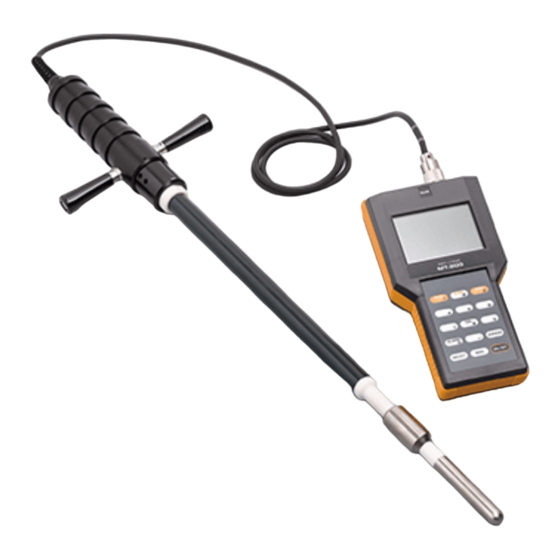
3. Part names <Main unit> <Accessories> Connector Display Bar sensor (PU-360) Shoulder strap Control panel 1.5 V batteries (AA alkaline) x6 Operating Manual Battery cover (back) -
Page 8: Display
4. Display Calibration curve name Calibration curve number Set value for the alarm Battery indicator Moisture value Number of measuring Bar graph... -
Page 9: Description Of Main Unit Keys (Control Panel)
5. Description of Main Unit Keys (control panel) * The numerical keys from 0 to 9 are used for number input. Some keys combine numerical input and other functions.functions. Functions Turns the power “ON” and “OFF”. <Control panel> Adjusts a moisture value bias. Selects a sample number. Averages measured values. Enters a minus correction value. -
Page 10: Before Measuring
6. Before Measuring (1) The unit is powered by six 1.5 V batteries (AA, alkaline). Remove the rear battery cover, place the batteries into the compartment taking care to correctly orient the positive "+" and negative "–" terminals. Then attach the battery cover. is displayed when the batteries become low. Replace all six with new batteries. -
Page 11: Directions
7. Directions 7-1. Measurement (1) Press the key to turn on the power. All elements of the LCD will be displayed for about 3 seconds. Subsequently, "calibration curve name," and "%" will be displayed. * At this time, if the display shows something other than the above, this unit may be in the abnormal state. Refer to “9. Warnings and Errors" on page 22. - Page 12 (3) Insert the bar sensor into wood chips. * When the bar sensor is inserted, push the sensor firmly into wood chips to place more than half of the sensor in the chips. If insertion is not deep enough, contact between the bar sensor and wood chips is not sufficient and an accurate measurement result may not be obtained. * Do not stir, twist, or wrench wood chips with use of the bar sensor in a reckless manner. Failure to observe this may apply excessive load to the bar sensor and accordingly cause damage to it. In addition, the state of contact with a sample significantly changes, which may greatly affect a measurement result. (4) Press the key. The decimal point will blink. After approximately 3 seconds a “beep” will sound and the “Measurement number”, “Moisture value”, and “Bar graph” will be displayed. * The bar graph will display up to 50% in units of 2%.
- Page 13 (5) Remove the bar sensor from wood chips. At this time, the moisture value remains on the display. To continue to make further measurements, start the procedure from the step “(3) Insert the bar sensor into wood chips" on page 12. When measurement is completed, press the key to turn off the power.
-
Page 14: Average Display
7-2. Average display Pressing the key when the number of measurements is from 2 to 9 displays "measurement number" and "average value". At this time, “measurement number” and “average value” remain displayed, but if a measurement is continuously made, “measurement number” will be 1. * If the number of measurements exceeds 9, the measured value up to that point resets and measurement starts from measurement number 1. -
Page 15: Continuous Measurement Mode Setting
7-3. Continuous measurement mode setting If the continuous measurement mode is selected, measurements can be made without pressing the key for each measurement. (1) Continuous measurement mode setting In the step "7-1. Measurement (4)" on page 12, pressing the key causes the decimal point to blink and display the moisture value and bar graph. -
Page 16: Moisture Content Value Correction
7-4. Moisture Content Value Correction The moisture value scale of this unit is created by statistically processing the relationship between the drying method and electric resistance. However, depending on various conditions, there are cases where the standard measurement method and the moisture value do not agree. In such cases, a moisture value bias can be adjusted (–9.9 to 9.9%) by the following method. -
Page 17: Setting The Alarm
7-5. Setting the Alarm When wood chips having moisture higher than the set moisture value are measured, a buzzer sounds to issue an alarm. (1) Press the key. The numbers to the right of “ALARM” will blink. (2) Enter the alarm value. Enter a 2-digit number. To enter “20%”, press the keys in succession. -
Page 18: User Calibration Curve And Moisture Value Bias Adjustment Function
8. User Calibration Curve and Moisture Value Bias Adjustment Function Calibration curves are created with plural samples in order for this unit to support measuring many different types of wood chips. However, wood chips have individual differences depending on producing areas and tree species. Therefore, our created calibration curves do not apply to some samples. In such a case, this function allows a user to create user original calibration curve for your sample and accordingly allows a user to conduct measurement with higher accuracy by adjusting moisture value bias. The example of the graph at right shows that the <Example of user calibration curve>... - Page 19 Regarding user's sample for user adjustment: (1) Measurement by using a base method such as drying method (2) Measurement by using this unit A difference between the measurement value by the base method and the measurement value before correction is checked after conducting the measurements mentioned above, and the correction coefficients, A and B, are obtained from the results. Regarding how to obtain the correction coefficients, A and B, please prepare on your own, for example, use a regression formula. * The user calibration curve function does not include the temperature correction function. Therefore, when the measurement of (2) mentioned above is conducted, conduct measurement by using 1.0 and 0.0 for the default correction coefficients A and B respectively of user calibration curves in the temperature environment to...
- Page 20 Ex.) When 1.4 and 3.0 are entered into the correction coefficients A and B respectively of the user calibration curve No. 03 (1) Press the key to turn on the power. All elements of the LCD will be displayed for about 3 seconds. After that, "CUT" and "%" are displayed. (2) Press the key, and the unit will be the calibration curve input mode.
- Page 21 (4) Enter a number for the correction coefficient A (0.1 to 1.9). The default value is "1.0". In this case, "1.4" is entered for the correction coefficient A. Successively press keys in the order of → (5) Enter a number for the correction coefficient B (-9.9 to 9.9). The default value is "0.0". In this case, "3.0" is entered for the correction coefficient B. Successively press keys in the order of → (6) Af ter the entr y is completed, the unit is in the state where the registered calibration curve is selected. Pressing the key enables measurement.
-
Page 22: Warnings And Errors
9. Warnings and Errors The following warnings and errors are displayed when an abnormality is present in this unit or the measurement condition. Display Description -5℃ This indication is displayed when the temperature of this unit decreases to -5°C or less. It is measurable. 50℃... - Page 24 Caution ● It is strictly prohibited to transfer part or all of this manual without permission. ● The contents of this manual are subject to change without notice. ● The appearances, screens, etc. of the product and accessories displayed on this manual may differ from the actual ones, however, operations and functions are not affected. ● All efforts have been made to ensure the contents of this manual are accurate. However, if you notice any part to be unclear, incorrect, omitted, or the like in this manual, please contact us. ● Be aware that we are not liable for the effects resulting from opera- tions according to this manual regardless of the items above. 060274...
Need help?
Do you have a question about the MT-200 and is the answer not in the manual?
Questions and answers