Table of Contents
Advertisement
Advertisement
Table of Contents

Related Manuals for MFZ Ovitor CS 300


Summary of Contents for MFZ Ovitor CS 300
- Page 1 Operating Instructions for Control CS 300 CS 300 Gate Controls / Rev.D 5.6 – 1...
-
Page 2: Table Of Contents
CHECK Indicates a check to be performed. REFERENCE Reference to separate documents which must be complied with. ☞ Action request − List, itemisation ➔ Reference to other sections of this document 2 – CS 300 Gate Controls / Rev.D 5.6... -
Page 3: General Safety Instructions
Use for the intended purpose − EN 12978 (Safety devices for power operated doors and The CS 300 control is only intended for controlling door gates - Requirements and test methods) systems with the use of operators with an electronic end position system (AWG absolute value encoder). -
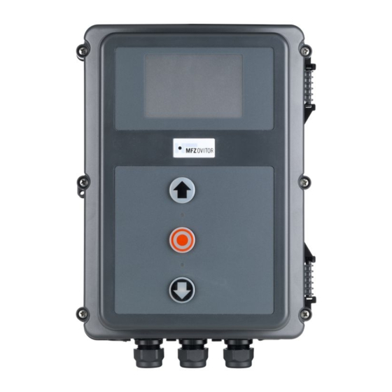
Page 4: Product Overview
− CS 300 control with LCD monitor in housing − CS 300 control with LED module for setting the OPEN end Committee for Workplaces (Ausschuss für Arbeitsstätten - position and the CLOSED end position... - Page 5 (on the LCD monitor) Programming button (P) (on the LCD monitor) 400 V 230 V The position of the jumper must take into account the power supply voltage and the motor voltage. CS 300 Gate Controls / Rev.D 5.6 – 5...
-
Page 6: Initial Operation
− The command and safety devices are installed and ready for operation. − The control housing with the CS 300 control is installed. REFERENCE The relevant manufacturers’ instructions must be adhered to for the installation of the door, the MFZ motor, and the Detailed circuit diagram for mains connection and command and safety devices. - Page 7 RS 485 B GROUND RS485 A Safety chain output Sockets B (absolute value encoder only) C: Thermal element in door operator D: Emergency manual operation (emergency hand crank or emergency hand chain) CS 300 Gate Controls / Rev.D 5.6 – 7...
- Page 8 Impulse button sequence control Connection examples for command devices (terminal block X3) OPEN / STOP / CLOSE buttons - Impulse button 6-lead solution - CLOSE button - OPEN button - STOP button 8 – CS 300 Gate Controls / Rev.D 5.6...
- Page 9 - Drive-through photocell - 24 V DC / 250 mA Terminal block X4 Three-wire NPN photocell for external switching devices (connection to terminals 1 and 2) - Three-wire NPN photocell CS 300 Gate Controls / Rev.D 5.6 – 9...
- Page 10 Initial operation Light curtain connection Connection of programmable inputs Terminal block X4 The CS 300 control has one programmable input for which various functions can be selected. ➔ “9.2 Input operating mode“ Light curtain OSE (optosensor) (parameter PRESS/REL = MOD4) Terminal block X4 The connecting cable (A) can be plugged in.
- Page 11 Press the programming button again for more than 1.6 seconds. When the LED lights up for approximately 4 seconds, all of the memory spaces have been deleted. The deletion procedure can be cancelled by briefly pressing the programming button. CS 300 Gate Controls / Rev.D 5.6 – 11...
-
Page 12: Setting The End Positions
− If an end position is corrected, the ADJUSTMENT mode can be exited by pressing button (P) once the teaching-in of the special end position has been completed. 12 – CS 300 Gate Controls / Rev.D 5.6... - Page 13 All parameters are reset to the original factory settings. − Only the S-POINT1 position can be reached as a part opening run. ➔ “9.2 Input operating mode“ CS 300 Gate Controls / Rev.D 5.6 – 13...
-
Page 14: Programming
The OPEN and CLOSED end position has not been The operating mode that the control is operating in is shown programmed in this door position. by the LEDs. − In AUTOMATIC mode there is no LED flashing. − In ADJUSTMENT mode at least one LED is flashing. 14 – CS 300 Gate Controls / Rev.D 5.6... - Page 15 The control has four modes of operation with the LCD moni- In the DIAGNOSIS operating mode, door-specific checks can tor: be queried. 1. AUTOMATIC 2. ADJUSTMENT Display: 3. INPUT − Displays the checks 4. DIAGNOSIS − Displays the status of the checks CS 300 Gate Controls / Rev.D 5.6 – 15...
-
Page 16: Navigator (Lcd Monitor Only)
Navigator (LCD monitor only) 16 – CS 300 Gate Controls / Rev.D 5.6... - Page 17 CS 300 Gate Controls / Rev.D 5.6 – 17...
-
Page 18: Overview Of Functions
During the opening phase, a 3-digit numerical value is shown in the lower right corner of the display. This numerical value is an indicator for the current torque and serves as a basis for setting the power monitoring. ➔ “9.2 Input operating mode“ 18 – CS 300 Gate Controls / Rev.D 5.6... - Page 19 The open time (if programmed) continues as usual. The open time is cut short after the photocell (X4 / 1-4) has been passed. The door closes immediately. This function is also active when the open time = 0. CS 300 Gate Controls / Rev.D 5.6 – 19...
- Page 20 0 – 8190 4050 S-POINT2 Setting intermediate CLOSE switching point (PART DOWN) 0 – 8190 3950 ➔ “6.3 Setting the intermediate positions of the electronic end position system using the LCD monitor“ 20 – CS 300 Gate Controls / Rev.D 5.6...
- Page 21 Impulse operation for OPEN + CLOSE with light curtain If the light curtain is interrupted in the OPEN end position, the open time (if programmed) will not restart but will continue to elapse. CS 300 Gate Controls / Rev.D 5.6 – 21...
- Page 22 MOD 1 OPEN MOD1: Photocell not activated MOD2: When the photocell is activated during the CLOSED end position and the S-POINT2 position, the door system stops. The red traffic light is ON. The S-POINT2 is automatically set to CLOSED end position + 600 inc. 22 – CS 300 Gate Controls / Rev.D 5.6...
- Page 23 Intermediate OPEN position to OPEN end position The relay closes the contact when the door is in the area between the OPEN end position and the intermediate OPEN position (PART UP). CS 300 Gate Controls / Rev.D 5.6 – 23...
- Page 24 Closing edge safety device actuated The relay opens the contact when the closing edge safety device is actuated. An error in the closing edge safety device or an unsuccessful test is shown via MOD5. 24 – CS 300 Gate Controls / Rev.D 5.6...
- Page 25 The relay is switched on with a 1 second time lag once the mains voltage is switched on and remains on continuously provided that the mains power supply is not interrupted. MOD 29 Relay OFF The relay is generally switched off; the contact is always open. CS 300 Gate Controls / Rev.D 5.6 – 25...
- Page 26 1 x OPEN + 1 x CLOSE = 1 cycle Counts only if the travel cut-out points are reached. Shows position information of absolute Displays the current transmitted value value encoder 26 – CS 300 Gate Controls / Rev.D 5.6...
-
Page 27: Error Messages And Rectification
– The power monitoring has been triggered. – Check the door for any mechanical impairment or damage. After rectifying the cause of the error, the power supply to the control must be turned off once! CS 300 Gate Controls / Rev.D 5.6 – 27... -
Page 28: Technical Data
Temperature range: Operation: -10°C … +45°C Storage: -25°C … +70°C Air humidity: Up to 80% with no condensation Vibrations: Low-vibration mounting, e.g. on a masonry wall 28 – CS 300 Gate Controls / Rev.D 5.6... -
Page 29: Maintenance
− Only approved parts may be installed. − All maintenance work must be documented. − Replaced faulty parts must be disposed of properly in accordance with the materials they contain and local regulations. CS 300 Gate Controls / Rev.D 5.6 – 29... -
Page 30: Ec Declaration Of Conformity
Household and similar electrical appliances - Safety - Part 1: General requirements DIN EN 60335-2-103: 2003 Household and similar electrical appliances - Safety - Part 2-103: Particular requirements for drives for gates, doors and windows 30 – CS 300 Gate Controls / Rev.D 5.6... - Page 31 CS 300 Gate Controls / Rev.D 5.6 – 31...
-
Page 32: Appendix
14. Appendix 14.1 Overview of connections Terminal block X5 (potential free switch contact) - relay 1 - relay 2 - relay 3 - relay 4 400V/50Hz/3/N/PE 400V/50Hz/3/N/PE 32 – CS 300 Gate Controls / Rev.D 5.6... - Page 33 (connection to terminals 1 and 2) - 24 V DC - A 8.2 kOhm resistor must be - STOP switch connected in series - The input parameter SEP TEST must be switched on white green brown CS 300 Gate Controls / Rev.D 5.6 – 33...
- Page 34 34 – CS 300 Gate Controls / Rev.D 5.6...
- Page 35 CS 300 Gate Controls / Rev.D 5.6 – 35...
- Page 36 #340061...
Need help?
Do you have a question about the CS 300 and is the answer not in the manual?
Questions and answers