
Subscribe to Our Youtube Channel
Related Manuals for MFZ Ovitor CS 300 RM


Summary of Contents for MFZ Ovitor CS 300 RM
- Page 1 Operating Instructions for CS 300 RM Controls CS 300 RM Gate Controls Rev. B 1.0 – 1...
-
Page 2: Table Of Contents
Using the equipment for its intended purpose The CS 300 RM control unit is intended exclusively for the purpose of controlling tubular drives that have mechanical limit switch systems. -
Page 3: Overview Of Products
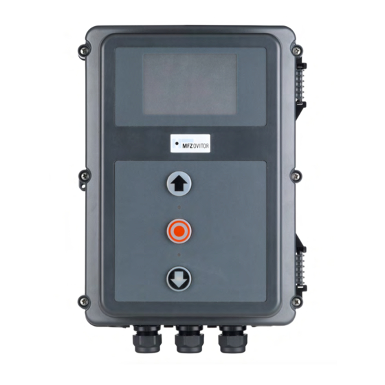
− CS 300 RM control unit with LCD monitor in housing − EN 13241-1 (Products without fire resistance or smoke − CS 300 RM control unit with LED module for setting the control characteristics) OPEN and CLOSED door positions (no further settings are −... - Page 4 (SKS) – illumina- ted when SKS is working Safety circuit status message – lights up when the safety circuit is closed 4A fuse 4 – CS 300 RM Gate Controls / Rev. B 1.0...
-
Page 5: Initial Operation
All control voltage inputs are devices, the relevant manufacturer’s instruc- separated galvanically from the mains power tions are to be adhered to. supply. CS 300 RM Gate Controls / Rev. B 1.0 – 5... - Page 6 - 24 V DC / 250 mA sequence control button or selector switch effective in down direction for external switching devices (connection to terminals 1 and 2) white green brown 6 – CS 300 RM Gate Controls / Rev. B 1.0...
- Page 7 - - 24 V DC / 250 mA Klemmleiste X4 ( mit Vorendschalter für Reversierabschaltung) - before-end switch Terminal block X4 (for 3-wire light barrier) - 3-wire light barrier CS 300 RM Gate Controls / Rev. B 1.0 – 7...
- Page 8 OPEN / STOP / CLOSE buttons (4-lead solution) - CLOSE button - impulse button - OPEN button - STOP button Connection: Connect any installed command and safety devices to the control unit. 8 – CS 300 RM Gate Controls / Rev. B 1.0...
- Page 9 CS 300 RM Gate Controls / Rev. B 1.0 – 9...
-
Page 10: Programming With The Led Module
The door is closed. The CLOSED limit switch has been reached. The door is between end positions. No limit switch has been reached. The OPEN and CLOSE limit switches have been interrupted (illogical state = TERM SWITCH FAIL). 10 – CS 300 RM Gate Controls / Rev. B 1.0... - Page 11 Press the (-) button to drive the door to the desired end position in the CLOSE direction. Adjust the mechanical limit switches. Change to AUTOMATIC mode by pressing the (P) button. Warning! The door can be damaged if driven beyond the end position. CS 300 RM Gate Controls / Rev. B 1.0 – 11...
-
Page 12: Programming With The Lcd Monitor
Programming with the LCD Monitor Overview of the LCD monitor Key: Operating mode / Diagnosis info Parameters / AUTOMATIC Diagnosis info STANDBY (+) button (-) button (P) button Jumper 12 – CS 300 RM Gate Controls / Rev. B 1.0... - Page 13 In ADJUSTMENT mode, the door is driven to the OPEN/CLO- SED end positions in deadman mode and the mechanical limit switches are set. Display: - Displays the operating status The external buttons have no function. CS 300 RM Gate Controls / Rev. B 1.0 – 13...
-
Page 14: Navigator (Lcd Monitor Only)
Navigator (LCD monitor only ) 14 – CS 300 RM Gate Controls / Rev. B 1.0... - Page 15 CS 300 RM Gate Controls / Rev. B 1.0 – 15...
-
Page 16: Overview Of Functions
The door is driven to the OPEN end position MAIN UP MANUAL The door is driven to the CLOSED end position MAN CLOSE MANUAL The door is stationary STANDBY 16 – CS 300 RM Gate Controls / Rev. B 1.0... - Page 17 Activation of the optoelectronic transmission system MOD21: Test of draw-in protection before door opening run (additional module required) MOD22: Test of external safety devices before door closing run (additional module required) CS 300 RM Gate Controls / Rev. B 1.0 – 17...
- Page 18 The pre-limit switch CLOSE is set automatically to the CLOSED end position + 600. SKS LEAD MOD1: No function MOD 1 MOD 1 MOD2: Leading light barrier (MFZ) MOD 2 18 – CS 300 RM Gate Controls / Rev. B 1.0...
- Page 19 The relay closes the contact when the door is in the area between the CLOSED end position and the pre-limit position CLOSE.* * Only possible if an external pre-limit switch (MOD 1) is connected to the SU/WI input (X4 9+10). CS 300 RM Gate Controls / Rev. B 1.0 – 19...
- Page 20 (zero current brake). In order to stop the door more smooth- ly at the OPEN end position, the switching contact is not switched at the OPEN end position (OPEN TIME). 20 – CS 300 RM Gate Controls / Rev. B 1.0...
- Page 21 The duration of the activation must be set in the transmission system. This activation results in a closing run delay of approx. 0.5 seconds. MOD 28 Relay OFF The relay is always open. CS 300 RM Gate Controls / Rev. B 1.0 – 21...
- Page 22 - Stop systems of drive OFF: interrupted (fault) BES CLOSE Pre-limit (before end) switch CLOSE OFF: actuated not actuated CYCLE Door cycle counter Display shows the number of door cycles 22 – CS 300 RM Gate Controls / Rev. B 1.0...
-
Page 23: Error Messages And Rectification
CLOSE end position profile - Check the setting for the CLOSE end position After rectifying the cause of the fault, the controls must be disconnected briefly from the mains! CS 300 RM Gate Controls / Rev. B 1.0 – 23... -
Page 24: Technical Data
-25 °C ... +70 °C Air humidity: Up to 80%, non condensing Vibration: Low vibration mounting, e.g. on a masonry wall Protection category: IP 65 Weight: Approx. 1.8 kg 24 – CS 300 RM Gate Controls / Rev. B 1.0... -
Page 25: Ec Declaration Of Incorporation
Generic standards - Emission standard for residential, com- mercial and light-industrial environments EN 60335-1 Household and similar electrical appliances - Safety EN 60335-2-103 Particular requirements for drives for gates, doors and win- dows CS 300 RM Gate Controls / Rev. B 1.0 – 25... -
Page 26: Appendix
13. Appendix Overview of connections Terminal block X5 (potential-free switch contacts) - relay 1 - relay 2 - relay 3 - relay 4 230V/50Hz 26 – CS 300 RM Gate Controls / Rev. B 1.0... - Page 27 - An 8.2 kOhm resistor must be - STOP button - GND connected in series - 24 V DC - The input parameter SKS TEST must be switched on white green brown CS 300 RM Gate Controls / Rev. B 1.0 – 27...
- Page 28 #1700018454 #148984...
Need help?
Do you have a question about the CS 300 RM and is the answer not in the manual?
Questions and answers