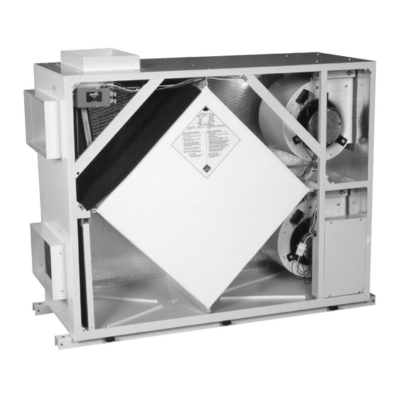
Summary of Contents for Venmar 1200 cfm
- Page 1 Light Commercial Heat Recovery Ventilators Installation, Operation and Service Instructions VB0003 VB0002 600 cfm 700 cfm VB0001 1200 cfm 06/00 04597...
-
Page 2: Table Of Contents
1 Safety Considerations ..........3 2 Installation 2.1 Inspection . -
Page 3: Safety Considerations
UNIT 600 cfm/700 cfm 14" x 8" (356 x 203mm) 1200 cfm 20" x 8" (508 x 203mm) NOTE: Duct sizes are for connection purposes only. Ducts should be sized to keep noise and pressure drop to a minimum. -
Page 4: Internal Grilles And Diffusers
Appendix C. All ports on the 600 cfm and 1200 cfm units have 1" (25mm) flanges to facilitate the installation of the ductwork. Please note that the "Fresh Air from Outside"... -
Page 5: Electrical Connections
Exhaust Only Defrost or Recirculation Defrost (via the recirculation module - 600 cfm and 1200 cfm units only). In cold temperatures, defrost cycles will remove frost from the heat exchanger to maintain good operation. -
Page 6: Remote Wall Control (Optional)
Recirculation Defrost Module (Optional - Factory Installed) The Recirculation Defrost Module is only available with the 600 cfm and 1200 cfm units. The defrost cycle is electronically controlled in response to the outside temperature 23°F to -22°F (-5°C to -30°C). -
Page 7: Balancing Procedure
A medium efficiency filter for the supply air stream is available from your supplier. This filter is disposable and should be replaced when it becomes dirty. VL0001 600 cfm and 1200 cfm 1. Washable foam filter 2. MEF filter - optional 1 or 2 VL0002A... - Page 8 600/1200 cfm ONLY: (CAUTION: 120VAC) Check for 120 volt output across the White/Black wires. If 120 volt can be measured at the motor, replace the motor.
-
Page 9: Appendix A - Mounting Diagrams
VD0002A Rubber Vibration Dry Contacts Isolater VD0003A Appendix A Mounting Diagrams 600 cfm and 1200 cfm Recirculation Module (Factory Installed) U Channel (Supplied by others) (Factory Installed) Rubber Vibration Isolator (Supplied by others) -
Page 10: Appendix B - Unit Dimensions
Appendix B Unit Dimensions B-1: 600 cfm (without recirculation module) Page 10... - Page 11 Appendix B Continued Unit Dimensions B-2: 600 cfm with recirculation module (factory installed) Page 11...
- Page 12 Appendix B Continued Unit Dimensions B-3: 1200 cfm (without recirculation module) Page 12...
- Page 13 Appendix B Continued Unit Dimensions B-4: 1200 cfm with recirculation module (factory installed) Page 13...
- Page 14 Appendix B Continued Unit Dimensions B-5: 700 cfm Page 14...
-
Page 15: Appendix C Flow Station Positions
VP0001A Flow Measuring Station (FMS) Min.12" (304mm) Canvas Vibration Isolator VP0002A Appendix C Flow Station Positions 600 cfm and 1200 cfm Reverse Door Option Flow Measuring Station (FMS) Canvas Vibration Isolator 700 cfm Dry Contacts Min. 30" (762mm) Page 15 Min. -
Page 16: Appendix D - Drain Connections
Appendix D Drain Connections 600 cfm and 1200 cfm Note: All hose, pipe & couplers to be 3/4"NPT supplied by others Coupler Plastic Hose T D i 3/4" NPT Coupler Plastic Hose Water Trap To Drain Plastic Drain Fittings Copper or... -
Page 17: Appendix E - Terminal Control Diagrams
E-1: Terminal Label A low voltage remote control wiring interface is provided on the unit. The connections for the low voltage remote wiring are located on two terminals adjacent to the exhaust fan outlet (or adjacent to the supply fan outlet on the 700 cfm unit). All field installed wiring must be low voltage class II. - Page 18 The illustration below shows a factory installed jumper and programmable timer option. NOTE: An occupied timer or sensor device cannot be used with the push button or pollutant wall controls. JUMPER (factory installed) NSB Timer Venmar PN 1604128 WALL CONTROL Black Green Yellow OCCUPIED TIMER/ SENSOR...
-
Page 19: Appendix F - Electrical Connection Diagrams
Appendix F Electrical Connection Diagrams Control Box Assembly 600 cfm and 1200 cfm VE0001A Low Speed Setting Wire Connections 600 cfm and 1200 cfm 12 pin 2 pin Low Speed (Red) Med Speed (Blue) Remove power before installing or removing... -
Page 20: Appendix G - Make-Up Heat Requirements
Appendix G Make-up Heat Requirements 600 cfm and 700 cfm 1200 cfm Page 20... -
Page 21: Appendix H - Wiring Diagrams
Appendix H Wiring Diagram Wiring Diagram for 600 cfm unit SPEED R2-1 AUTOTRANSFORMER Page 21 C L M H C L M H... -
Page 22: Wiring Diagram
Wiring Diagram for 700 cfm unit Appendix H Continued Wiring Diagram Page 22... - Page 23 Appendix H Continued Wiring Diagram Wiring Diagram for 1200 cfm unit SPEED R2-1 AUTOTRANSFORMER Page 23 C L M H C L M H...
-
Page 24: Appendix I Trouble Shooting
SYMPTOMS Inside air is too dry Persistent condensation on windows, walls, ceilings, etc. Unit stops functioning Air from supply diffusers too cold Imbalance of supply and exhaust air Unit makes annoying noise Heat exchange core freezing up For technical assistance and warranty information, Appendix I Trouble Shooting POSSIBLE CAUSES...


Need help?
Do you have a question about the 1200 cfm and is the answer not in the manual?
Questions and answers