
Related Manuals for olympia electronics BSR-1000


Summary of Contents for olympia electronics BSR-1000
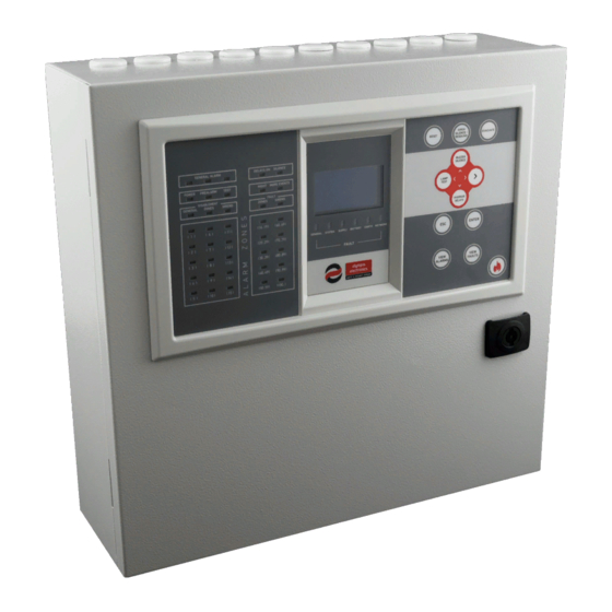
- Page 1 BSR-1000, BSR-1001, BSR-1002, BSR-1004 Analogue Addressable Fire Alarm Panel 1, 2 and 4 loops Installation Programming Operation WARNING!!! READ THIS MANUAL PRIOR TO ANY INSTALLATION OR USE...
-
Page 2: Table Of Contents
Date 22/4/2021 Document number 921100400_09_005 Page 2 of 71 Index 1 General Information ---------------------------------------------------------------------------------------------------------------------- 5 General description -------------------------------------------------------------------------------------------------- 5 Safety ------------------------------------------------------------------------------------------------------------------- 5 Indicators and Controls --------------------------------------------------------------------------------------------- 6 Control panel’s front ------------------------------------------------------------------------------------------- 6 1.3.1 Control panel’s keypad ---------------------------------------------------------------------------------------- 7 1.3.2 1.3.3 LED indicators --------------------------------------------------------------------------------------------------- 8 2 Functions 10 Control panel operating states ----------------------------------------------------------------------------------- 10... - Page 3 Date 22/4/2021 Document number 921100400_09_005 Page 3 of 71 4.4.2 Connecting conventional sirens ---------------------------------------------------------------------------- 38 Panel network connections --------------------------------------------------------------------------------------- 39 General connections diagram ------------------------------------------------------------------------------------ 40 Other connections -------------------------------------------------------------------------------------------------- 41 5 Technician Menu ------------------------------------------------------------------------------------------------------------------------- 43 Test Menu ------------------------------------------------------------------------------------------------------------ 45 5.1.1 Walk test --------------------------------------------------------------------------------------------------------- 45 5.1.2 All zones in test ------------------------------------------------------------------------------------------------ 45 5.1.3...
- Page 4 4 of 71 7 BSR-100X PC software application ------------------------------------------------------------------------------------------------- 63 Programming the panel -------------------------------------------------------------------------------------------- 63 Loop calculation ----------------------------------------------------------------------------------------------------- 66 Battery Calculation-------------------------------------------------------------------------------------------------- 67 8 BSR-1000 Repeater panel ------------------------------------------------------------------------------------------------------------- 67 General ---------------------------------------------------------------------------------------------------------------- 67 Functions-------------------------------------------------------------------------------------------------------------- 68 Installation ------------------------------------------------------------------------------------------------------------ 68 Wiring ------------------------------------------------------------------------------------------------------------------ 68 Setup repeater network -------------------------------------------------------------------------------------------- 68 8.5.1...
-
Page 5: General Information
(for Windows PC). The communication between PC and control panel is via a USB cable. The repeater BSR-1000 along with the BSR-100x fire detection panel series, allow the user to execute basic functions for controlling, monitoring as well as reading the event log of the system. All, through the built-in keypad and the LCD graphic display. -
Page 6: Indicators And Controls
Date 22/4/2021 Document number 921100400_09_005 Page 6 of 71 1.3 Indicators and Controls The control panel’s LCD screen displays information regarding the current state of the fire detection system. The front face is also equipped with LED indicators for essential indications (alarm, fault, status, zones, etc.). -
Page 7: Control Panel's Keypad
Date 22/4/2021 Document number 921100400_09_005 Page 7 of 71 1.3.2 Control panel’s keypad Resets the panel from alarm state to RESET quiescent, clears current faults SIREN Stops or resumes sirens during SILENCE / alarm mode RESOUND Evacuation of the building. Manual EVACUATE activation of all alarm outputs BUZZER... -
Page 8: Led Indicators
Date 22/4/2021 Document number 921100400_09_005 Page 8 of 71 1.3.3 LED indicators The LED indicators are divided into groups, according to their purpose. Their color also define their event type, red LEDs indicate alarm, yellow LEDs indicate status or fault, green LED indicates the mains power. In details, LEDs from top to bottom are: System is in fire GENERAL ALARM... - Page 9 Date 22/4/2021 Document number 921100400_09_005 Page 9 of 71 On the figure below appear the LED indicators below the screen. All of them refer to specific faults of the control panel (according to the description) and are yellow. GENERAL FAULT General panel fault System fault SYSTEM FAULT...
-
Page 10: Functions
Date 22/4/2021 Document number 921100400_09_005 Page 10 of 71 2 Functions 2.1 Control panel operating states The operating states of the control panel are the following: Α) Quiescent Β) Prealarm C) Alarm D) Fault 2.2 Quiescent state The state where there are not any current alarms, prealarms or fault events is called quiescent state. The message “SYSTEM READY”... -
Page 11: Alarm State
Date 22/4/2021 Document number 921100400_09_005 Page 11 of 71 Figure 2-2.Prealarm on main screen 2.4 Alarm state If a detection device triggers a fire alarm signal, the red "GENERAL ALARM" indicator is being lit. On the first row the message “X – ALARMS” is shown, where X represents the number of the current alarms. Figure 2-3.Alarm on main screen The second and the third row, describe the first and the last alarm event respectively. -
Page 12: Access Level Functions 1 (Access Level 1)
Date 22/4/2021 Document number 921100400_09_005 Page 12 of 71 Access Level Functions 1 (Access Level 1) This level refers to the functions that a simple user can do directly via the keypad while on main screen. No code (password) is required for these functions “BUZZER SILENCE”: On the event of a fault, or an alarm, if this key is pressed, the built-in buzzer stops sounding. -
Page 13: Events Menu
Date 22/4/2021 Document number 921100400_09_005 Page 13 of 71 More information regarding the options in the main menu: • VIEW DISABLEMENT: View all disabled segments of the fire detection system. • USER MENU: This menu includes a set of settings only accessible by user with access level “2”. •... -
Page 14: Information
Date 22/4/2021 Document number 921100400_09_005 Page 14 of 71 2.7.3 Information By selecting “INFORMATION” the menu displays the available options on the first screen below. There are additional options following that will appear by scrolling down the menu with down key, as shown in the following screens. - Page 15 Date 22/4/2021 Document number 921100400_09_005 Page 15 of 71 The “ZONES IN ALARM” option will display all zones that are in alarm state. If no zone is in alarm, the screen on the right will be displayed. The “ZONES IN FAULT” option will display the zones that are in fault. If no zones are in fault the screen on the right will be displayed.
- Page 16 Date 22/4/2021 Document number 921100400_09_005 Page 16 of 71 By selecting “LOOPS” option, the screen on the right appears. The first line, “STATUS”, shows if the loop is present and active. The rest of the lines, indicate how many of each point type are registered into this loop.
- Page 17 Figure2-24.Ethernet adaptor By selecting “TECHNICIAN INFO” option, the screen on the right appears. The OLYMPIA ELECTRONICS S.A. contact info is displayed by default. This information can be changed via PC software or web interface by the installer, in order to provide the desired company’s name and telephone number.
- Page 18 Date 22/4/2021 Document number 921100400_09_005 Page 18 of 71 By selecting “PANEL SOFT VERSION” option, the screen on the right appears, displaying the firmware installed on the panel, for the CPU and the loop circuits. The last line also displays the panel’s serial number. Note! On the screen it is only displayed the firmware for the installed loops.
-
Page 19: User's Menu
Date 22/4/2021 Document number 921100400_09_005 Page 19 of 71 3 User’s Menu This chapter contains information for user access with access level 2 (code protected). Press Enter key once to enter main menu. User menu option appears on the monitor (figure 4-1). Figure3-1.Main Menu Then select “USER MENU”... - Page 20 Date 22/4/2021 Document number 921100400_09_005 Page 20 of 71 Figure 3-3.User’s menu diagram In this menu, the following basic functions can be done • RESET the system (clears current alarms, prealarms and faults) • SIREN SILENCE in case of an alarm event, to mute audible alarm. •...
-
Page 21: Enable / Disable Segments
Date 22/4/2021 Document number 921100400_09_005 Page 21 of 71 3.1 Enable / Disable segments Via the "ENABLE" and “DISABLE” options, the user can enable or disable any segment of the control panel, as shown in figures 3-4. By disabling a segment, all faults and alarm signals received by that segment will be ignored by the control panel. -
Page 22: Delays Menu
Date 22/4/2021 Document number 921100400_09_005 Page 22 of 71 3.2 Delays Menu Via “DELAYS” option the user can activate or deactivate time delays in general. If a delay has been applied to at least one segment of the control panel, then DELAYS ON indicator will light yellow. By activating the delays, this setting will be applied permanently. -
Page 23: Backlight Mode
Date 22/4/2021 Document number 921100400_09_005 Page 23 of 71 Figure3-11.Change time By selecting “WORKING DAYS” the screen on the right is shown. Use up/down keys to select day and click right key to enable or disable this day. Filled box equals to enable. When set press Enter to save. -
Page 24: Pc Communication
Date 22/4/2021 Document number 921100400_09_005 Page 24 of 71 3.6 PC Communication The “PC COMMUNICATION” option is used to download panel’s data to a PC via USB cable, running the BSR-100X software application. This function may seem useful, in order to keep event logs, keep a record of current configuration as a backup or to gather and send useful data to manufacturer in terms of troubleshooting. -
Page 25: Operating Via Pc (Ethernet)
Date 22/4/2021 Document number 921100400_09_005 Page 25 of 71 3.7 Operating via PC (Ethernet) This chapter contains information on how to monitor and configure the panel remotely via a common web browser (web interface), on a Local Area Network (Ethernet connection required). 3.7.1 Control panel web interface To operate the panel via PC (web interface) no special software is required. -
Page 26: View Disablement
Date 22/4/2021 Document number 921100400_09_005 Page 26 of 71 3.7.3 View disablement If there are any disabled segments on the system, by clicking on this link, all disabled segments will be displayed in separate lines. 3.7.4 Information The “INFORMATION” link will lead to a submenu with multiple available informational options. These options are described below: 3.7.4.1 Information Panel This option will display the page below, with the most significant data of the control panel (hardware... - Page 27 Date 22/4/2021 Document number 921100400_09_005 Page 27 of 71 3.7.4.4 Information Loops This option will display loop information, regarding the connected point types to each one of them. 3.7.4.5 Information Points This option will open the page below. On the input boxes you can enter the point’s loop and address. By clicking “OK”...
- Page 28 Date 22/4/2021 Document number 921100400_09_005 Page 28 of 71 3.7.4.7 Information Extra Relays Same as panel relays, the extra relays option contains similar information for the extra relays settings. Extra relays belong to peripheral equipment and are not pre-installed in the control panel. 3.7.4.8 Information Conventional Sirens This page displays all settings for the conventional sirens.
-
Page 29: All Events
Date 22/4/2021 Document number 921100400_09_005 Page 29 of 71 3.7.5 All events All panel’s events are appearing in chronological order. Due to the high capacity of recorded events (7k), the events are divided into pages. 3.7.6 User’s menu By selecting “USER MENU” the systems asks for user code (access level 2): Enter the user’s code and click “SEND”. -
Page 30: Installation
USB connection with the use of the PC software application BSR-100X. The program is free of charge and can be downloaded from the official site of Olympia Electronics S.A. https://www.olympia-electronics.com/en/support/software All the following connections must be made while the control panel is deactivated, disconnected from mains power supply and batteries. -
Page 31: Control Panel Installation
Date 22/4/2021 Document number 921100400_09_005 Page 31 of 71 4.3 Control panel installation The control panel installation must be done by trained personnel exclusively. Do not touch, add or remove boards or components, perform connections or do other modifications, while mains power supply is connected. -
Page 32: Connecting The Mains Power Supply Cable (220-240V Ac)
Date 22/4/2021 Document number 921100400_09_005 Page 32 of 71 Figure4-2.Panel mountings and holes The panel must be placed at least 1m above floor level and 1m bellow roof level and at the minimum distance of 30cm from other devices. No other supply lines should cross the wall behind the panel except the panels own power supply. -
Page 33: Connecting The Batteries
Date 22/4/2021 Document number 921100400_09_005 Page 33 of 71 Figure 4-3.Mains power supply connection Caution! 1. Any assignment of installation, repairs or electrical equipment maintenance must be executed with both mains power supply and batteries disconnected. 2. Connect the batteries and enable mains power supply to the control panel only after all other cable connections have been completed. -
Page 34: Wiring
Date 22/4/2021 Document number 921100400_09_005 Page 34 of 71 4.4 Wiring For compliance with the electromagnetic compatibility (EMC) requirements, the connections of the peripheral devices to the panel must be done with shielded cables. Every cable’s shield must be connected to the closest “Protective Earth” ground, to achieve the minimum electrical distance possible. -
Page 35: Loop Connections
Date 22/4/2021 Document number 921100400_09_005 Page 35 of 71 4.4.1 Loop Connections All models of the BSR-100X family, BSR-1001, BSR-1002 and BSR-1004 share the same architecture, thus same loop connection method. They differ only on the available loop connection outputs (1, 2 or 4). The output connections, maximum consumption and the connection diagrams that are going to be mentioned in the next paragraphs are common to all panels. - Page 36 Date 22/4/2021 Document number 921100400_09_005 Page 36 of 71 Figure 4-6.Detector base connections BSR-6155, BSR-6160 and BSR-6157 36 / 71...
- Page 37 Date 22/4/2021 Document number 921100400_09_005 Page 37 of 71 Figure 4-7.Connecting the manual call point (MCP) BSR-5136 Figure 4-8.Connecting addressable siren BSR-5132 Figure 4-9.Connection of input/output unit BSR-8120 37 / 71...
- Page 38 Date 22/4/2021 Document number 921100400_09_005 Page 38 of 71 4.4.2 Connecting conventional sirens Figure4-10.Conventional sirens connection There are four outputs to the main board for conventional sirens connection marked as «SIR1», «SIR2», «SIR3» and «SIR4». Each output can supply a current up to 300mA and it is monitored for short-circuit and open circuit.
- Page 39 Date 22/4/2021 Document number 921100400_09_005 Page 39 of 71 4.5 Panel network connections A network of panels can support up to 4 interconnected control panels. Each control panel owns a unique address. The master panel owns the address 1 and the subpanels have the addresses 2, 3 and 4. The interconnection wire must be twisted pair (2-core).
- Page 40 Date 22/4/2021 Document number 921100400_09_005 Page 40 of 71 4.6 General connections diagram A theoretical general connections diagram is depicted below: Figure4-12.General connections diagram 40 / 71...
- Page 41 Date 22/4/2021 Document number 921100400_09_005 Page 41 of 71 4.7 Other connections The following section contains information for other available connections in the control panel. For each of the following connection a separate cable must be used (don’t use multicore cables to connect multiple outputs).
- Page 42 Date 22/4/2021 Document number 921100400_09_005 Page 42 of 71 adaptor set up the IP address of the control panel via Technician menu and connect the network cable to the corresponding RJ45 socket on the adaptor (figure 4-14). Printer: To connect a printer adaptor, disconnect batteries and mains power and place it on the corresponding connector on the CPU board (same position of figure 4-14).
- Page 43 Date 22/4/2021 Document number 921100400_09_005 Page 43 of 71 5 Technician Menu The following chapter includes all information for commissioning a new installation of a BSR-100X Analogue Addressable Fire Alarm Panel. The technician menu contains a set of commissioning functions, parameters and other general settings and is code protected (access level 3).
- Page 44 Date 22/4/2021 Document number 921100400_09_005 Page 44 of 71 Figure5-3.Technician menu diagram In the following sections a detailed description for every available option appears. 44 / 71...
- Page 45 Date 22/4/2021 Document number 921100400_09_005 Page 45 of 71 5.1 Test Menu This submenu is used during periodic maintenance of the system to set the fire detection equipment in test mode in order to confirm functionality. The available options are the following on figure 5-4. WARNING! By enabling test mode to a control panel the system’s fire detection ability is inhibited until test mode is terminated.
- Page 46 Date 22/4/2021 Document number 921100400_09_005 Page 46 of 71 5.1.4 Device LED Address “DEVICE LED ADDRESS” option starts a countdown procedure of 25 minutes while every connected fire detection device indicates its address by a special flashing pattern that is repeating. 3burst short flash 2 seconds gap number of flashes multiplied by tens (with 1s gap between)
- Page 47 Date 22/4/2021 Document number 921100400_09_005 Page 47 of 71 Additional information for the selected points can be displayed by pressing the View Alarms key once. The additional information is “OPERATING HOURS” and “ALARM COUNTER” of the specific point. Figure5-10.Check point 2 5.2.2 Check loop communication “LOOP COMMUNICATION”...
- Page 48 Date 22/4/2021 Document number 921100400_09_005 Page 48 of 71 5.2.5 Check voltage outputs “VOLTAGE OUTPUTS” will display the screen on the right, for the technician to select one of the 24V generic outputs for testing. During testing the selected output will switch off for 6 seconds and switch on again.
- Page 49 Date 22/4/2021 Document number 921100400_09_005 Page 49 of 71 5.3 Setup menu This submenu contains a series of configuration options for almost every segment of the fire detection system. 5.3.1 Points ”POINTS” option will prompt for selecting a specific point address. First select the point’s loop and then its address.
- Page 50 Date 22/4/2021 Document number 921100400_09_005 Page 50 of 71 The preset name of the point will be “POINT Y.XXX” where Y the point’s loop and XXX the point’s address. The preset zone of each point will be equal to its loop (e.g. point 3.025 zone will be zone 3). The first line, “CURRENT ADDRESS”...
- Page 51 Date 22/4/2021 Document number 921100400_09_005 Page 51 of 71 5.3.4 Change point address This option may be used in order to change a specific point’s address, in purpose of replacement, adding new point or other modifications on the installation. This function will send a command to change the address of all connected devices to the selected loop.
- Page 52 Date 22/4/2021 Document number 921100400_09_005 Page 52 of 71 choices are appeared NO/YES, if you select YES then by pressing the SIREN SILENCE button the output will stop. By selecting NO the output will stop only after a RESET. - Pre-alarm: Same choices with the alarm menu. - On a specific zone: Select task, delay (from NO up to 10 minutes) and YES or NO at SIREN SILENCE.
- Page 53 Date 22/4/2021 Document number 921100400_09_005 Page 53 of 71 5.3.9 Panel Network “PANEL NETWORK” submenu contains the options listed on the screen on the right. Figure5-26.Panel network First option, “PANEL ADDRESS” will open an input window to configure the control panel’s address within the network of panels. Each address must be unique.
- Page 54 Date 22/4/2021 Document number 921100400_09_005 Page 54 of 71 5.3.10 Loops “LOOPS” option displays the screen shown on the right. Via this selection screen, the technician can register / unregister loop circuits. Use up/down keys to navigate between the loops and right key to select or unselect activation.
- Page 55 Date 22/4/2021 Document number 921100400_09_005 Page 55 of 71 5.3.13 Indication of points “INDICATION OF POINTS” option is used to enable or disable the red LED indicator blinking on the addressable points. Useful on areas (e.g. hotels) that LED blinking might bother inhabitants or other special events.
- Page 56 Date 22/4/2021 Document number 921100400_09_005 Page 56 of 71 5.4.2 Change technician code “CHANGE TECH CODE” option will display the screen on the right, asking the technician to enter a new code for access level 3. After inputting the code, the panel asks to enter the new code again for confirmation.
- Page 57 Date 22/4/2021 Document number 921100400_09_005 Page 57 of 71 The first option “ETHERNET PCB” is used to enable / disable the Ethernet adaptor. Enable the Ethernet adaptor only when a GR-8530 Ethernet adaptor card is installed into the panel. Figure5-43.Ethernet PCB Next option, “IP ADDRESS”...
- Page 58 Date 22/4/2021 Document number 921100400_09_005 Page 58 of 71 5.4.8 Annual check date “ANNUAL CHECK DATE” option indicates the next scheduled maintenance date. Figure5-48.Annual check date 5.4.9 Reset defaults “RESET DEFAULTS” clears memory and restores all configurations back to factory default values. The only exceptions are certain hardware configurations: Loops (enabled/disabled), External PCB function, Ethernet PCB (enabled/disabled).
- Page 59 Date 22/4/2021 Document number 921100400_09_005 Page 59 of 71 5.7 PC Communication The “PC COMMUNICATION” option is used to download/upload configurations from or to a PC via USB cable, running the BSR-100X software application. When selected, a confirmation message as the screen on the right will be displayed.
- Page 60 Date 22/4/2021 Document number 921100400_09_005 Page 60 of 71 The menu design is similar to the corresponding panel’s menu. Although some functions can be made exclusively by using the Ethernet menu, (e.g. “CHANGE INFORMATION”). The following paragraph is describing the new options available to configure via web interface that were not present via the keypad.
- Page 61 Date 22/4/2021 Document number 921100400_09_005 Page 61 of 71 6 Initial installation procedure The initial installation of the BSR-100X Analogue Addressable Fire Alarm systems comes with an advanced “tool” that automatically sets the address of each point in a loop, to save time and make installation easier.
- Page 62 No faults, alarms or prealarms should be active and the control panel’s screen should display the message “SYSTEM READY”. Full access to the BSR-100X control panel’s programming options can be granted via the BSR-100X PC software application by Olympia Electronics. You can download the software directly by the official Olympia Electronics website for free: https://www.olympia-electronics.com/en/support/software See chapter 7 for further information.
- Page 63 Date 22/4/2021 Document number 921100400_09_005 Page 63 of 71 7 BSR-100X PC software application 7.1 Programming the panel In order to connect the BSR-100X control panel to a PC, a Mini-USB 2.0 cable will be needed. The Mini- USB port on the control panel is located on the back side of the CPU board, above the lock mechanism. See the photos below: Photos: Mini-USB connector on the CPU board position.
- Page 64 Date 22/4/2021 Document number 921100400_09_005 Page 64 of 71 When the BSR-100X control panel is detected, the message “Ready” will be displayed on the bottom line of the “Synchronize with Panel window” To receive control panel configuration file, click on “Receive” button.
- Page 65 Date 22/4/2021 Document number 921100400_09_005 Page 65 of 71 Now proceed with configuring other parameters, such as detector alarm limits and names. Click on a loop entry on the left column. All registered points in this loop, appear on the right section of the screen. When an entry is selected, its data is displayed on a form below: Double click on a point to edit name and parameters.
- Page 66 Date 22/4/2021 Document number 921100400_09_005 Page 66 of 71 After finishing with the configurations (names, zones, tasks, behavior etc.), save a copy of the configuration file: File > Save As Keep this configuration file copy on a safe location which can be later used to restore this data. To transfer the new configuration file, go to: Panel Communication >...
- Page 67 8 BSR-1000 Repeater panel 8.1 General The BSR-1000 is a repeater for BSR-100x series panels and allows the general monitoring of the system. The BSR-1000 through its build-in screen and keypad can show panel network events, current and recorded, and user can perform basic control of panel network.
- Page 68 Page 68 of 71 8.2 Functions Similar to BSR-1001-2-4 the BSR-1000 has the same functionality as far as the indicators, screen and keypad concerns, as well as the Menu structure.The only difference is some functions limitation, i.e. the screen on the right is shown on menus that repeaters cannot access, preventing wrong actions.
- Page 69 Date 22/4/2021 Document number 921100400_09_005 Page 69 of 71 9 Technical Characteristics – Properties BSR-1001 BSR-1002 BSR-1004 Analogue Addressable Analogue Addressable Analogue Addressable Description Fire Alarm Panel Fire Alarm Panel Fire Alarm Panel 1 Loop / 128 Zones 2 Loops / 128 Zones 4 Loops / 128 Zones Mains power input 220-240VAC/50-60Hz...
- Page 70 Date 22/4/2021 Document number 921100400_09_005 Page 70 of 71 Mains input: 4A/250V (Fast) TR5 – non replaceable Fuse type Battery: 900mA self resettable – non replaceable Operating -5 to 40 °C temperature range Relative humidity Up to 95% non-condensing Construction ABS –...
- Page 71 Olympia Electronics reserves the right to repair or to replace the returned goods and to or not charge the buyer depending on the reason of defection. Olympia Electronics reserves the right to charge or not the buyer the transportation cost.
Need help?
Do you have a question about the BSR-1000 and is the answer not in the manual?
Questions and answers