
Related Manuals for olympia electronics BSR-100 Series


Summary of Contents for olympia electronics BSR-100 Series
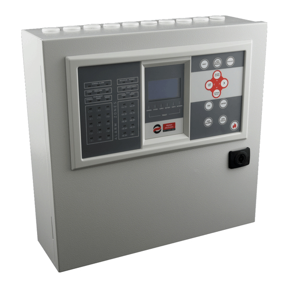
- Page 1 FIRE Addressable Fire Detection System BSR-100X Quick Installation Guide & Generic Design 921100400_90_001_QG_EN...
-
Page 2: Maintenance
Calculator ” tool shall be used for cable selection period of warranty is specified in the official according to your installation size. All features catalogue of Olympia Electronics and also in the and indications are in accordance with European technical leaflet, which accompanies each standards ΕΝ... - Page 3 PREREQUISITE REQUIREMENTS AND PRELIMINARY PROCEDURES Loop Calculation with PC-1004 Download, install and run the PC-1004 software. Prepare and set all parameters for each point. Use the Tools->Loop Calculator and choose the option “Get from the Loop”. Check all the desired setup parameters –...
- Page 4 Correct cable and connection We recommend: - FIP200 - MICC - PYROFIL. Choose the correct cross section for each zone. Refer to the previous table. All points must be connected according to the following diagrams. Fig.1 Mounting holes and inside overview Fig.2 Battery Connection 921100400_90_001_QG_EN...
- Page 5 Fig.3 General connection diagram 921100400_90_001_QG_EN...
- Page 6 Fig.4 Loop Diagram Fig.5 Detector base connections BSR-6155, BSR-6157 and BSR-6160 (Optional BSR-5072 Remote LED) 921100400_90_001_QG_EN...
- Page 7 Fig.6 Connection of manual call point BSR-5136 Fig.7 Addressable Siren connection 921100400_90_001_QG_EN...
- Page 8 Fig.8 Input/Output unit BSR-8120 connection Fig.9 Conventional Siren connection Fig.10 Panel Network connections 921100400_90_001_QG_EN...
- Page 9 Fig.11 Extra Relay BS-613 placement( Optional/On Demand) Fig.12 External modules placement Note: Place the Ethernet Adaptor all the way to the left. i.e use the first 10 pins. 921100400_90_001_QG_EN...
- Page 10 STEP BY STEP INSTALLATION ISTRUCTIONS Mount the panel on a surface, able to support 20kgs at least. Perform all the requisite connections and wirings according to all the above figures. If shielded cable, it must be attached to the EARTH TERMINAL connector of the panel. ...
-
Page 11: Installation Procedure
INSTALLATION PROCEDURE • Perform AUTOADDRESSING POINT. This action erases all previous addresses and it does re-addressing of the points. TECHNICIAN MENU Common use: New panel and loop installation / First operation. <SETUP> • Perform POINT DETECTION, only if the existing addresses need to be read and registered to the system. -
Page 12: Troubleshooting
• Enable or Disable point LEDs by the option INDICATION OF POINTS. TECHNICIAN MENU <SETUP> • Set EXTERNAL PCB FUNCTION for Modbus, Printer or NONE. TECHNICIAN MENU <GENERAL SETTINGS> • Select MODBUS ADDRESS from 1 to 247. TECHNICIAN MENU <GENERAL SETTINGS>... - Page 13 CHARGER FAULT One or both batteries need to be Replace the batteries. replaced. POINT X.XX 1) AUTOADDRESSING or POINT 1)Perform AUTOADDRESSING or ADDRESSING have not been NOT REGISTERED POINT DETECTION –see page 11 for performed. the difference– 2) The 24V external power supply of 2) Make sure the external power one or more BSR-8120 devices, have supply of all the BSR-8120 had been...
Need help?
Do you have a question about the BSR-100 Series and is the answer not in the manual?
Questions and answers