Table of Contents
Advertisement
Quick Links
Advertisement
Table of Contents

Related Manuals for DARAY X340

Summary of Contents for DARAY X340
- Page 1 X340 LED Examination Light Operating & Installation Manual QAM.X340.0519.9...
- Page 2 Page 1 of 43...
-
Page 3: Table Of Contents
Table of Contents 1. Introduction ..............4 1.1 Supported Lights ............5 2. Technical Specifications ..........6 2.1 Pre-Installation Responsibilities and component packing list ... 7 2.2 Pre-Start Checks ............8 3. Operation ..............9 3.1 Range of Motion ............9 3.2 Powering On &... - Page 4 4.6.3 Lighting configuration ........... 28 4.6.4 Affixing the Ceiling plate ........28 4.6.5 Wiring and transformer layout ......... 29 4.6.6 Downtube adjustment and installation ....... 30 4.6.7 Light head and arm fixing ........33 5. Maintenance ............... 34 5.1 Maintenance schedule ..........34 5.2 Safety Precautions ............
-
Page 5: Introduction
(without the need for secondary filtering) with virtually no heat. Multiple mounting options are available. The X340 features a high-output intensity controlled by a button on the rear of the light head. The light operates from a safe low voltage produced by a mains transformer, and has a swivelling, spring-balanced arm system and a rotating head to allow accurate and stable positioning of the light-patch. -
Page 6: Supported Lights
X340 LED Mobile Weighted Base Light X340LE1 X340 LED Hardwired W3 BESA Wall Mounted Light X340LE2 X340 LED Hardwired W4 Spreader Plate Wall Mounted Light X340LE3 X340 LED Hardwired W5 Panel Mounted Light X340LE4 X340 LED Hardwired W6 Wall Mounted w/ Integral PSU... -
Page 7: Technical Specifications
2. Technical Specifications Light Source Light Intensity (Lux) @ 0.5m 64,000 Lux ±5% Light Intensity (Lux) @ 0.75m 30,000 Lux ±5% Light Intensity (Lux) @ 1.0m 17,000 Lux ±5% Light Intensity Adjustment Range 10% - 100% Colour Temperature (Kelvin) 4,300K ±500 Colour Rendering Index (CRI) Colour Rendering (R9) @ 0.5m: 90mm... -
Page 8: Pre-Installation Responsibilities And Component Packing List
2.1 Pre-Installation Responsibilities and component packing list This document is a guide to the steps that need to be performed to correctly install the X340 Examination light. However, the work required to be performed is the responsibility of the owner or designated contractor/s. -
Page 9: Pre-Start Checks
X340LE3 Qty. X340LE4 24V Plug top transformer Light head and spring rigid arm system incl. base box (transformer integrated) Panel Mount Bracket (W5) Microfibre cloth Light head and rigid arm system User Manual Microfibre cloth User Manual 2.2 Pre-Start Checks Please check that the power cable is without visible damage, harsh folds, knots or cuts in the rubberised coating. -
Page 10: Operation
3. Operation 3.1 Range of Motion The full range of motion between the X340 Range varies. This is an image depicting the range of motion on a standard wall mount fitting. X340LW Page 9 of 43... - Page 11 X340LE4 Page 10 of 43...
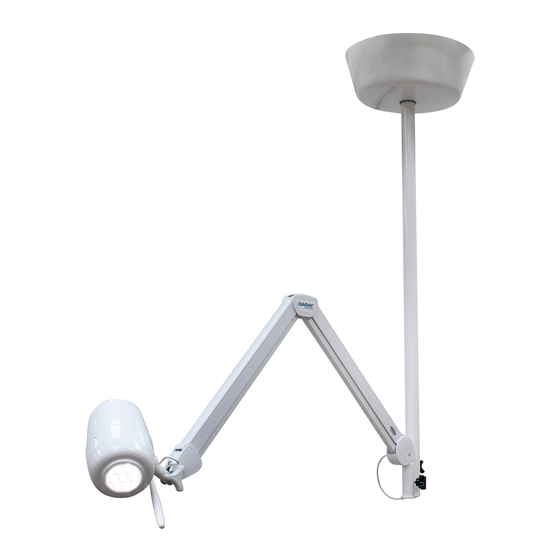
- Page 12 This is an image depicting the range of motion on a standard ceiling mount fitting. Ceiling Mount Cover Retainer Ring X340LC Light head Tension Adjustment Downtube Rigid Arm Downtube Extension Page 11 of 43...
-
Page 13: Powering On & Variable Intensity
3.2 Powering On & Variable Intensity The X340 uses a single button on the back of the head to power the light on and off. This switch also controls the lights variable intensity Press the power button to power ON or OFF. -
Page 14: Adjusting The Light Head
3.3 Adjusting the Light Head The X340 head is secured using a pivot adjustment knob on the right hand side of the arm, near the head. This also controls the forward and backward motion of the head itself. DO NOT confuse this with the tension adjustment knob on the left side – see section 5.6 (Page 35). -
Page 15: Operating The Downtube
3.4 Operating the Downtube On the ceiling mounted version (X340LC), the inner extension arm in the downtube extends to a maximum of 300mm – see below image. This extension is controlled by a thumb screw located around the back of the primary downtube. -
Page 16: Installation
4. Installation 4.1 Wall mounted versions Compatible versions: X340LW / X340LE1 / X340LE2 / X340LE3 / X340LE4 The wall bracket needs to be true on the vertical plane. PIVOTW2: supplied with PIVOTW3: supplied X340LW with X340LE1 PIVOTW4: supplied with X340LE2 PIVOTW5: supplied Page 15 of 43 with X340LE3... -
Page 17: Considerations
It may be necessary to adjust this height, if there are specific medical procedures the light will be used for. If in doubt consult the end user or DARAY. When installing the bracket take consideration of where you want the light head to sit when in its lowest position. -
Page 18: X340Lw - Placement And Installation
UK wall socket. Please note, under no circumstances should this product be connected directly to the Mains electrical supply, this product requires a Low Voltage Connection only and must only be used with a Daray Certified Power Adapter. Page 17 of 43... - Page 19 The light can now be tested by connecting the DC jacks and applying power. Press the switch on the head to power your light on. See page 12 Check arm and head for smooth and correct movement. Your new DARAY light is now ready for use.
-
Page 20: X340Le1 - Placement And Installation
4.1.3 X340LE1 – Placement and Installation Remove the light from its packaging. This version includes our PIVOTW3 BESA mounting bracket, for mounting to a BESA box. Ensure the BESA back-box is mounted between recommended 850- 1100mm from the floor to the underside of the bracket – dependent on couch height. -
Page 21: X340Le3 - Placement And Installation
4.1.5 X340LE3 – Placement and Installation Remove the light from its packaging. This version includes our PIVOTW5 panel mounting bracket. Fit front bracket and rear plate to pre-drilled panel. Fit light spigot into bracket and pass cable through to the rear of panel. - Page 22 CAUTION: This product must be earthed. Check you have all of the items included in the checklist on Page 7 Note the mounting position advice and warnings offered in Section 4.1.1 Considerations on page 10 Flush-fitting the wall box (chased-in cables): ...
-
Page 23: Rail Mounted Version (X340Lr)
4.2 Rail mounted version (X340LR) Remove the light from its packaging. If you have also purchased our XRAIL accessory, hold the rail against the selected location on the wall, bearing in mind the final position and range of travel of the light-head required to project its light patch where it will be needed. -
Page 24: Mobile Version (X340Lm)
Mark the position on the desk for mounting. Use screws the fix the bracket securely. Fit the spigot on the end of the light arm into the top of the clamp, make sure it is fully secured in place. Apply the power cable, and power the light on. - Page 25 Insert the orange IEC cable into the black power supply attached to the base upstand. The light can now be tested by connecting the DC jacks between the power supply and the light, and applying power. Press the switch on the head to power your light on.
-
Page 26: Optional Battery Back-Up
4.5 Optional battery back-up Connect the supply cable from the 5525 OUT socket of battery back-up unit, insert the yellow end into the upstand terminal. Connect the plug top transformer to the 5521 IN/OUT connector on the battery backup unit. ... -
Page 27: Ceiling Mounted Version (X340Lc)
If in doubt please consult a qualified electrician. Minimum Room Requirements The X340 ceiling mounted light has an internal extension that protrudes out from the main downtube, considerations for this and the amount of downtube required to fixing into the ceiling plate means that the minimum length of downtube is 500mm. -
Page 28: Attachment Methods And Void Suspension
After concluding the structural stability of the ceiling structure it will be necessary to assess the construct and decide on the best course of action for installing the ceiling plate. There are various different methods for loading the plate onto the ceiling, below are various example methods that can be used. -
Page 29: Lighting Configuration
DARAY’s standard mounting recommendation is to have the ceiling plate directly bolted into the structure when possible. This would also be suitable for non-voided areas with use of a DARAY standard ceiling mount cover. -
Page 30: Wiring And Transformer Layout
Ideally the cable used to power the light should be of a 1.5mm twin and earth type. DARAY recommends that the power supplied uses an earthed switched fused spur, protected with a 3amp fuse. -
Page 31: Downtube Adjustment And Installation
4.6.6 Downtube adjustment and installation The downtube provided will be either 1m as standard or 2m (optional) maximum. It is DARAY`s recommendation that the bottom of the downtube is approximately 1900mm from the floor, therefore the minimum room height suitable for the ceiling mounted light is 2.4m. - Page 32 Once the downtube has been cut to length it will be necessary to de-burr the end of the pipe, we also recommend doing this to the inner and outer edges of the safety bolt’s drill hole as this will prevent damage to the cable. Before drilling the safety bolts hole, please direct spigot on the bottom the downtube toward the centre of the examination area to allow the best range of motion over the examination area.
- Page 33 Now you should put the rubber retainer ring onto the downtube followed by either the ceiling trim or ceiling mount cover. This is to allow the covers to be fixed into position after you have attached the downtube to the ceiling plate. Ceiling Mount Cover Suspended Ceiling Mount Cover...
-
Page 34: Light Head And Arm Fixing
The light can now be tested by applying power and pressing the power button on the back of the head. Check the arm and head for smooth and correct movement. Your new DARAY light is now ready for use. To gain full support of our warranty please fill in our warranty web form or contact DARAY by phone or email. -
Page 35: Maintenance
The proposed maintenance is only a suggestion. Depending on the use of the product and the operating environment, this may need to be revised more often. DO NOT ATTEMPT ANY FIXES BEFORE CONSULTING DARAY. If you cannot resolve a problem then please contact our helpline on 0800 878 9864 or email support@daray.co.uk... -
Page 36: Product Cleaning & Care Guidelines
Acetone-based cleaners (e.g. nail polish remover, Goo-off™) MEK (Methyl Ethyl Ketone) If you are unsure whether you are using the correct cleaning fluids on your DARAY equipment, please feel free to get in touch with us for advice. Page 35 of 43... -
Page 37: Detaching Parts
(as shown in section 4.6.5 – page 28). The fuse tray can easily be removed by hand and the fuse replaced. The fuse supplied is 1 amp and this can be ordered from DARAY using the code CS6144. -
Page 38: Rigid Arm Adjustments
5.6 Rigid Arm Adjustments The X340 light is mounted on spring-tensioned rigid arms which are balanced specifically to be able to be moved using a single finger touch. Your light will have been balanced during manufacture, so there should be no need for you to make any adjustments out of the box. -
Page 39: Troubleshooting Guide & Spare Parts
6. Troubleshooting Guide & Spare Parts Problem Possible Cause Corrective Actions Wall Version - Check the plug top adapter is plugged in and switched Power Supply on at the power socket. Press the button on the back of the On/Off/Intensity light head to check if the light will Button power on (if dimmed refer to poor... - Page 40 Cable Kit (mobile) DRK4177 1 Amp ceiling plate fuse CS6144 For any SPARE PARTS or TECHNICAL ISSUES phone DARAY’S Service Delivery Team on: +44 (0) 800 878 9864 Opening times 9am–5pm Monday to Thursday (excluding bank holidays) 9am-2:30pm on Friday Or email: support@daray.co.uk...
-
Page 41: Warranty Information
DARAY Ltd, please read the following information carefully. The DARAY Ltd returns policy provides guidance on when you can return goods we have supplied, and what you can expect from us once you do. To see our detailed returns policy and procedure visit www.daray.co.uk/returns... -
Page 42: Warranty Details
Direct damage to your property caused by the proven negligence of Daray. 6. This agreement does not give any rights other than those expressly set out above and in particular, Daray will not be responsible for any loss of income, profits or contracts or any direct or indirect consequential loss, damage caused to or suffered by the purchaser as a direct result of this agreement. - Page 43 Service Notes Page 42 of 43...
- Page 44 Page 43 of 43...
- Page 45 Page 44 of 43...
- Page 46 Page 45 of 43...
- Page 47 Page 46 of 43...
- Page 48 DARAY Ltd. Edison House Robian Way Swadlincote Derbyshire United Kingdom DE11 9DH +44 (0)800 878 9864 +44 (0)333 321 0973 sales@daray.co.uk www.daray.co.uk...
Need help?
Do you have a question about the X340 and is the answer not in the manual?
Questions and answers